 How to access the new feature
 Helpful hints and
tips
Helpful hints and
tips
Backward Compatibility
DataCAD 11 is compatible with the same drawing files, symbols, templates, line types,hatch patterns, fonts, and DCAL macros,as DataCAD versions 4 through 10.
Display Enhancements
DataCAD's graphic pipeline has been enhanced for improved performance. The time required for Panning, Zooming, Dynamic Panning, and Scroll Wheel Zooming has been significantly reduced. In addition, the Perspective Walk Through, Pan View setting is recognized when you use either the scroll wheel or the dynamic panning method to walk forward or backward or step up, down, left, or right respectively. A new menu item, Scroll Dist., has been added to the Perspective, Walk Through, Options menu to set the walk and step distance when you use the mouse to navigate in a perspective view.
Double-precision Database
12345678901234...
DataCAD 11 uses double-precision floating point math to calculate
and store values in the drawing database. Prior versions of DataCAD
had an effective accuracy of ~7 decimal places. DataCAD 11 has an effective
accuracy of ~14 decimal places. That means DataCAD 11 is now as accurate
as AutoCAD and you can work on much larger projects without
running into rounding issues, especially when importing large drawings.
Network Awareness
DataCAD can query other instances of DataCAD running on a network to determine whether or not a file is in-use. Every time you open a drawing, DataCAD records the date, time, username, and workstation name in a corresponding user (.U$R) file. If you try to open a drawing file that is in-use, DataCAD will only allow you to open a copy of the file.
Backup and Recovery
We revamped DataCADs backup and recover process to be more reliable and intuitive. Whenever you exit a drawing abnormally, DataCAD will automatically try to recover the most recent version of your file without prompting you with unnecessary warnings and options.
File Purge
DataCAD files are automatically purged of any unused data each time
you exit and save your drawing. In addition, a Purge dialog replaces
the Layer Utility macro, allowing you to create new drawings based on
a sub-set of an existing drawing.

Purge Drawing Dialog
To
access Purge Drawing options, select Purge... from the File menu.
Selecting saved views
or multi-scale plotting sheets will automatically select corresponding
layers.
Compressed Drawing Files
DataCAD 11 drawings are now stored in a compressed format making them roughly 1/5 the size of previous versions.
Drawing Session Backups
Drawing session backups is a new feature that allows you to configure DataCAD to automatically save up to 10 incrementally-named backup drawings. Session backups are only created each time you exit and save your drawing.

To
access Drawing Session options, go the Misc. tab of Program Preferences.
A new drawing session
is created only when you close and save your drawing.
You can have a maximum
of 10 drawing sessions per file.
Program Interface

DataCAD 11 features an updated program interface that provides Windows
2000-style properties and support for Windows XP Themes and "Skins".
You can position toolbars and menus where you want by tearing them off
and docking them to the top, bottom, left, or right side of the application
window. You can also place toolbars and menus outside of DataCAD to "float"
on the desktop, allowing you to resize the drawing area without adversely
affecting the user interface and to take advantage of dual monitor displays.
In addition, all of the interface elements in DataCAD 11 will inherit
the visual style of your current desktop theme.
Symbol Browser
 DataCAD
11 introduces an easier way to browse, select, and manage symbols. The
new Symbol Browser allows you to rapidly find, place, customize, and
manage symbols that you use in your drawings. Inserting a symbol into
your drawing involves little more than selecting it from the Symbol
Browser and dropping it where you want it. With just a few mouse clicks,
you can open the appropriate folder, display the symbols in the browser,
and select the ones you want to use into your drawing. If you developed
custom templates with older versions of DataCAD, you can open them in
the Symbol Browser, too. In effect, the Symbol Browser treats file folders
as templates that contain collections of symbols.
DataCAD
11 introduces an easier way to browse, select, and manage symbols. The
new Symbol Browser allows you to rapidly find, place, customize, and
manage symbols that you use in your drawings. Inserting a symbol into
your drawing involves little more than selecting it from the Symbol
Browser and dropping it where you want it. With just a few mouse clicks,
you can open the appropriate folder, display the symbols in the browser,
and select the ones you want to use into your drawing. If you developed
custom templates with older versions of DataCAD, you can open them in
the Symbol Browser, too. In effect, the Symbol Browser treats file folders
as templates that contain collections of symbols.
To
access the Symbol Browser, go to the View pull-down menu and select
Symbol Browser.
You can use the [Ctrl]
+ [T] shortcut to open and close the Symbol Browser.
Symbol Fields
It's now possible to assign an unlimited number of user-defined fields
to symbols for enhanced reporting. You're no longer limited to the five
default fields.

Symbol Field Editor
To
edit symbol fields, select Edit Fields from the Symbol Browser Options
menu.
Symbol Field Reporting
We've enhanced symbol reporting so you can run reports on all symbols
in the drawing instead of just the symbols in the active template. A
new dialog gives you access to report forms and displays an on-the-fly
preview of the results.

Symbol Report Form Dialog
To
access symbol reports, select Reports from the Symbol Browser Options
menu.
You can run reports
on any symbol you've placed in the drawing, not just the symbols displayed
in the Symbol Browser.
Symbol Text Attributes
 Text
attributes can be defined and added to symbols. This lets you use the
same symbol multiple times, supplying a unique text string for each
one. For example, you could use one desk symbol several times and label
them Jim's desk, Nancy's desk, and Bob's desk.
Text
attributes can be defined and added to symbols. This lets you use the
same symbol multiple times, supplying a unique text string for each
one. For example, you could use one desk symbol several times and label
them Jim's desk, Nancy's desk, and Bob's desk.
To
create a symbol attribute, go to the Text menu and select Sym Attrib.
A symbol can contain
an unlimited number of attributes.
Symbol Text Attribute Reporting
 Text
attributes can be defined and added to symbols. This lets you use the
same symbol multiple times, supplying a unique text string for each
one. For example, you could use one desk symbol several times and label
them Jim's desk, Nancy's desk, and Bob's desk.
Text
attributes can be defined and added to symbols. This lets you use the
same symbol multiple times, supplying a unique text string for each
one. For example, you could use one desk symbol several times and label
them Jim's desk, Nancy's desk, and Bob's desk.
To
access symbol text attribute reports, select the Extract Attributes
option from the Symbol Browser Options menu.
Drop Symbols On Polygons
 A
new option available for inserting symbols allows you to drop any item
such as a symbol directly on the surface of a polygon.
A
new option available for inserting symbols allows you to drop any item
such as a symbol directly on the surface of a polygon.
To
insert a symbol directly on to a polygon mesh, select Z Offset, On Polygon
from the insert symbol menu.
Note: Z Offset settings
Z-Base, Z-User 1, Z-User 2, and Z-Height are now toggles. So you can
easily insert symbols at the current Z-Base without having to change
the Z Offset value each time.
TIN Surface Modeler
 A
new TIN(Triangulated Irregular Network) surface modeler provides a comprehensive
array of three-dimensional site modeling tools. The TIN modeler can
connect a random series of survey points (3D markers) with triangular
polygons. Once the polygons are generated, you can calculate the surface
area of TIN models, use the flip valley option to flip the valley between
coincident polygon edges, or create roads, foundation cuts, etc. with
the 3D Knife. The drop point option lets you place 3D markers on the
surface of inclined polygons. You can create polyline contours from
polygon site models.
A
new TIN(Triangulated Irregular Network) surface modeler provides a comprehensive
array of three-dimensional site modeling tools. The TIN modeler can
connect a random series of survey points (3D markers) with triangular
polygons. Once the polygons are generated, you can calculate the surface
area of TIN models, use the flip valley option to flip the valley between
coincident polygon edges, or create roads, foundation cuts, etc. with
the 3D Knife. The drop point option lets you place 3D markers on the
surface of inclined polygons. You can create polyline contours from
polygon site models.

To
access the TIN surface modeler, go to 3D Entity, Polygons, TIN Surface.
Drop Point
You can place a three-dimensional marker on a polygon at an inclined
point.
To
drop a 3D marker on a polygon, go to 3D Entity, Polygon, Drop Point.
Make Contours
You can make a topological contour map based on a group of three-dimensional
points or polygons.
To
generate two-dimensional contours from a three-dimensional surface,
go to 3D Entity, Polygons, Gen. Contour.
Ruled Surface Modeler
 A
ruled surface function allows you to mesh polygon surfaces between Polylines
and Contours.
A
ruled surface function allows you to mesh polygon surfaces between Polylines
and Contours.
To
access the ruled surface modeler, go to 3D Entity, Polygons, Ruled Surf.
For the best results,
draw a polyline boundary and use Geometry, Offset to create two boundaries
to mesh together.
3D Knife
A three-dimensional knife allows you to interact with TIN surfaces
to create roads, sidewalks, and foundation cuts. You can use the knife
to cut out, raise, or depress irregular areas and paths on the building
site. Since DataCAD also calculates the volume of the affected area,
you can estimate the amount of fill that must be removed (if you are
digging for a foundation or a roadway) or added (if you are building
up part of the site). To differentiate the cut area, you can specify
a different color from the rest of the TIN model. Further, you can select
distinct colors for each level and/or side of the cut area.


To
access the 3D Knife, go to 3D Entity, Polygons, and select 3D Knife.
Note: You only have
to select the polygons that will be effected by the path to cut.
Sectioning Tool
You can easily create two-dimensional sections from three-dimensional
models using the new sectioning tool. Advanced options allow for automatically
hatching and updating sections. You can also create hidden line sections.
Straight, offset, and curved section paths are supported.
To
access the sectioning tool, go to 3D Edit and select Section.

Section Settings Dialog

Multi-View Windows
All-new multi-view windows provide up to 10 tear-off, resizable windows
you can use to store and display various views of your project.

To
access multi-view windows, go to the View pull-down menu and select
Toolbars...
You can use the [Ctrl]
+ [W] shortcut to quickly turn multi-view windows on and off.
Expanded Bitmap Support
The number of supported image formats has been increased to include
BMP, JPG, GIF, TIF, TGA, PNG, PCX, EPS, and PCD files.
To
insert a bitmap into your drawing, go to the Insert pull-down menu and
select Bitmap...
Stereolithography
You can export your DataCAD models to STL format for use with rapid
prototyping machines including 3D printers. You can also import STL
files into DataCAD from other programs.

To
export your model to STL format, go to the File pull-down menu and select
Export STL File...
To
import an STL file into your drawing, go to the Insert pull-down menu
and select STL File...
3D Studio
You can import 3DS files into your DataCAD drawings.
To
import a 3D Studio file into your drawing, go to the Insert pull-down
menu and select 3DS file.
Select Explode, and
toggle off Current Layer to distribute the objects material definitions
to individual layers.
WHIP!
DataCAD 11 adds support for DWF format so you can view and distribute
your drawings via the Internet.
To
export your drawing to DWF format, go to File, Export, DWF.
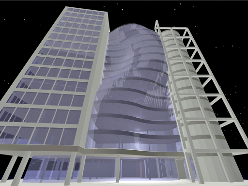
o2c Rendering
We've enhanced the interface for assigning materials to o2c objects so you can control the origin, angle, and scale of any bitmap texture. In addition, you are no longer limited to 32,768 polygons per material.
PDF w/ Layers
Drawing layers can now be included when you create a PDF file directly
from DataCAD. Note: Requires Adobe Reader version 6 or later to view
layers. However, PDF files created by DataCAD 11 can be read by Adobe
Reader versions 4 and 5.
To
create a PDF file with layers, select Save As from the print preview
window and enable Drawing Layers.
Context-sensitive Toolbar
A user-definable, context-sensitive toolbar automatically changes
to present related icons based on the menu you choose. A configuration
dialog allows you to easily set which toolbar is related to a particular
menu selection.


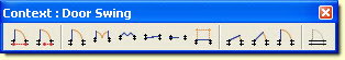


To
associate a toolbar with a DataCAD command, go to the View pull-down
menu, select Toolbars..., then Context.
Enhanced Keyboard Macros
User-defined keyboard macro sequences can now include up to 1,024 commands and there is no limit to the number of characters you can use in the sequence. We've also added a special PAUSE character so you can tell the macro to wait until you do something such as click or type. Go to the Help pull-down menu and select What's New? for more information.
Nested Aliases
You can call a command line alias by name when you define a macro sequence so you can take advantage of existing aliases.
Classic-style Menu Window


Classic Menu Window, Navigation Pad, Projection Pad, and Status Panel
are available. To enable these classic-style elements, go to View, Toolbars.
If you would also like to have the classic look of raised buttons, go
to the Interface tab in Program Preferences and check Classic Buttons.
Bitmap Orphans Manager
A new bitmap orphans manager allows you to redefine paths for bitmaps you've already inserted into your drawing.
Nested XREF Display Toggle
A new option allows you to disable the display of nested external references at the time you insert an XREF. You can also toggle the display of nested external references on a per XREF basis via the Reference File Manager or the context-sensitive pop-up menu. The display of nested references can be disabled globally with the Display Nested XREFs option in the Nested XREFs section of the Misc. tab of Program Preferences.
Duplicate XREFs Use Same Memory Space
Multiple XREFs of the same file now use a single memory space. Used in combination with the Display Nested XREFs toggle, you can significantly reduce the amount of memory required to open your drawings that contain XREFs.
Self-referencing XREFs Use Same Memory Space
Multiple self-referencing XREFs now use the same memory space so DataCAD no longer creates a new swap file every time you reference a drawing into itself.
Plot Scale Saved with GoTo Views
A new option, Save with GoTo Views, has been added to the Current Plot Scale section of the Misc. tab of Program Preferences. This lets you save the current plot scale with a GoTo View when you create it.
Global Line Overshoots
You can now set the line overshoot value globally so that it applies to all entities equally. The global line overshoot is scale-independent and is defined as a real-world, plotted distance. You can access the Overshoots menu from the Line Type menu. Note: Overshoot must be toggled on in the Display menu in order to view/plot line overshoots.
Contour Search Supports Line/Arc and Arc/Arc
The contour search routine has been updated to handle line/arc and arc/arc conditions that were not supported previously.
2-Line Trim Supports Line/Arc and Arc/Arc
The two line trim command has been updated to handle line/arc and arc/arc conditions that were not supported previously.
Embedded Line Types
Line Types (up to 255) are now stored in your drawing file. Now, you don't have to worry about providing custom line type definitions to your colleagues when you give them copies of your drawings. DataCAD 11.01.00 automatically converts your line type definitions from DCADWIN.LIN to individual .DLT files stored in \DataCAD\Support Files\Line Types.
Line Type Creator
Now, anything you draw can be converted into a new line type. The line type creator allows you to select entities in your drawing (up to 65,536) to define one segment of a custom line type. You can begin using your new line type immediately.
Line Type Manager
 A
line type manager has been added to the Line Type menu. Select Line
Manage from the Line Type menu to access a dialog for loading or re-loading
external line type definitions into your drawing. You can also set the
End Correction and Default Spacing for embedded line type definitions.
A
line type manager has been added to the Line Type menu. Select Line
Manage from the Line Type menu to access a dialog for loading or re-loading
external line type definitions into your drawing. You can also set the
End Correction and Default Spacing for embedded line type definitions.
Embedded Hatch Patterns (Optimized)
Embedded hatch patterns have been optimized to require less memory. DataCAD 11.01.00 automatically converts your hatch pattern definitions from DCADWIN.PAT to individual .DHP files stored in \DataCAD\Support Files\Hatch Patterns.
Hatch Pattern Manager
A hatch pattern manager has been added to the Hatching menu. Select
Manage from the Hatching menu to access a dialog for loading or re-loading
external hatch pattern definitions into your drawing. You can also set
the angle and scaling for embedded hatch pattern definitions.
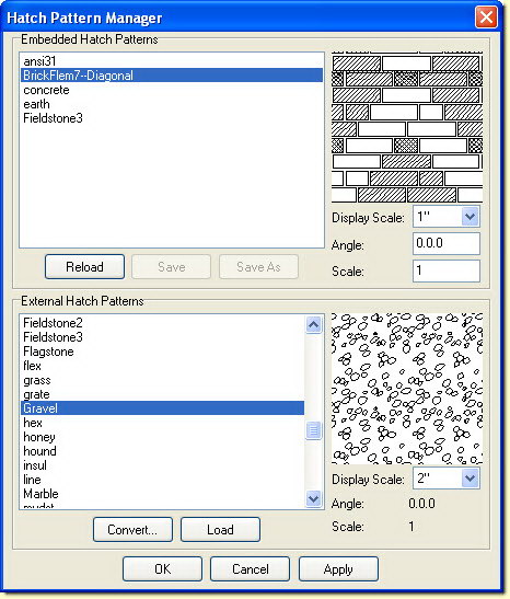
Hatch Pattern Manager Dialog
Screen Calibration
Using the Screen Calibration dialog, accessible from the Interface
Settings tab of Program Preferences, you can measure the test pattern
in either decimal inches or millimeters in order to adjust both the
screen scaling and aspect ratio.
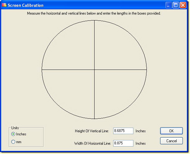
Screen Calibration Dialog
Enhanced Context-sensitive Menu
An Identify section has been added to the context-sensitive ([Ctrl] + Right-click) menu for quick access to Identify Set and Set All options. XREF-related options have been grouped together in an XREF Tools fly-out menu that provides quick access to the following options.


Revision History
Thank you for printing this page. Please feel free to contact us for further assistance. You can call our sales department at +1 (800) 394-2231, Monday through Friday from 8:00 a.m. to 5:00 p.m. Eastern time or send an e-mail message to info@datacad.com.