![]() Where to find the new feature
Where to find the new feature
![]() Helpful hints
Helpful hints
AutoCAD DXF/DWG Compatibility R2013-R2015
DataCAD 16 supports the ability to import and export AutoCAD R2013-R2015
files in DXF/DWG format. This enables you to collaborate and share files
with associates who use the latest version of AutoCAD and other CAD
software.
The DXF/DWG Translator has been optimized to reduce the size of exported
DXF/DWG files. When exporting to DXF/DWG files using the "On Layers"
option, only those symbols which are instanced on the exported layers
are included in the file header.
Productivity Enhancements


Associative Dimension Prefix and Suffix
Options to display "Prefix," “Dimension,” and "Suffix" have
been added to the "Dim Style" sub-menu of the Dimensions/Linear menu.
Their status and custom data is included with the collection of information
saved in the dimension style file (*.dimstyle).
Geometry/Tangents
The Geometry/Tangents function now supports the ability to select Associative
Dimensions. When you select an Associative Dimension, DataCAD rotates
the cursor to match the angle of the dimension line.
 New
Previous Selection Method
New
Previous Selection Method
Added a button labeled "Previous," which selects the previously selected
set of entities, to the "Mask" menu of each selection menu.
XREF Enhancements
Added the "Dynamic Snapping" setting (On or Off), found in the [Ctrl]
+ Right-click, XREF Tools context menu for XREFs, to the Reference File
Manager.
The "Nesting," "GTV Link," "Dyn. Snap," and "Smart Wall Hatch/Fill"
sections of the Reference File Manager are grayed out until you select
an XREF to modify. This works similar to the way the "Highlighting"
section works.
You now have the ability to disable XClips and SClips for the entire
drawing. [Ctrl] + Right-click in a blank section of the drawing area
to access the Drawing Context Menu. Un-check "XClips On" and/or "SClips
On" will disable display of XClips or SClips. DataCAD will display XREFs
and Symbols as if no XClips or SClips are assigned. The individual clipping
boundaries are retained.
Symbol Enhancements
When replacing or redefining a symbol, the name of the symbol is now
displayed on the "Message" toolbar at the bottom of the program interface.
DataCAD has a new "Auto Reload" option, located in the [Ctrl] + Right-click,
Symbol Tools context menu for symbols. When this option is checked,
DataCAD will automatically reload the symbol definition on the hard
drive for each instance of the selected symbol every time you open the
drawing. This setting is assigned and remembered on a per-symbol (but
not per-instance) basis. If a symbol marked for Auto Reload is not found
in the original location, DataCAD will display a warning message when
you open the drawing which notes the name and path of the missing symbol.
DataCAD will then display any instances of that symbol in the drawing
using the symbol definition from the drawing file header.
A new "Save As" command has been added to the context menu that appears
when you right-click on a symbol in the Symbol Browser. This enables
you to save a copy of the symbol to a different folder, or with a different
name.
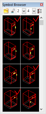 There
is also a new option labeled "Loaded Indicators" to the "Options" pull-down
menu at the top of the Symbol Browser. When enabled, a small check mark
is displayed in the upper right corner of cells on the Symbol Browser
displaying symbols that have been loaded in the header of the current
drawing.
There
is also a new option labeled "Loaded Indicators" to the "Options" pull-down
menu at the top of the Symbol Browser. When enabled, a small check mark
is displayed in the upper right corner of cells on the Symbol Browser
displaying symbols that have been loaded in the header of the current
drawing.
Drag-N-Drop
DataCAD now supports the ability to drag and drop any of the following
file types:
![]()
![]()
AEC/DC5
These files may be dropped onto the DataCAD start screen or
an open drawing to open them in new windows. Holding the [Ctrl] key
when dropping the file will import it into the active drawing. Holding
the [Alt] key when dropping the file will insert it as an XREF in the
active drawing.
![]()
DXF/DWG
These files may be dropped onto the DataCAD start screen or an open
drawing to open them in new windows. Holding the [Ctrl] key when dropping
the file will import it into the active drawing.
![]()
SketchUp - SKP
These files may be dropped onto an open drawing to insert them as a
Symbol. Holding the [Alt] key when dropping the file will insert it
as an XREF in the active drawing.
![]()
Notepad - TXT
These files may be dropped onto an open drawing to insert them as a
PText. The drop point is used the first point of the PText boundary.
If you hold the [Ctrl] and [Alt] keys when dropping the file, DataCAD
will prompt you to select the first point of the PText boundary.
![]()
Bitmaps (BMP/JPG/JPEG/GIF/TIF/TGA/PNG/PCX/PCD)
These files may be dropped onto an open drawing. DataCAD will use the
drop point as the first point of the boundary rectangle. If you hold
the [Ctrl] and [Alt] keys when dropping the file, DataCAD will prompt
you for the first point of the boundary.
![]()
Excel - XLS
These files may be dropped onto an open drawing to insert them as an
XREF.
![]()
![]()
![]()
![]()
o2c, ACO, 3DS, STL, DSF/SM3
These files may be dropped onto an open drawing to insert them as a
Symbol.
![]()
Metafiles (EMF/WMF)
These files may be dropped onto an open drawing to add vectors to the
drawing file.
Editing Tools
There is a new "Fit" sub-option to the "Copy" menu when "Array" is toggled
on. Use this command to copy selected entities in an array, but have
them fit within a specified area.
We have added a "Dynamic" option to the 2D and 3D Stretch commands.
2D lines, 3D lines, and (open) polylines are supported. After selecting
"Dynamic," click near the end point of the line or polyline you wish
to stretch. You may then reposition it dynamically using the rubber-band
method.
When using the "Point" selection method in the "Stretch" command and
then using the left mouse button to click on a point, DataCAD will select
all points that are within one pixel of the cursor position. This has
been enhanced such that if no point is found within one pixel, DataCAD
will now choose the closest available end point.
The "Stretch" command now supports the ability to select the quadrant
points of ellipses.
Two new fields for "X Radius" and "Y Radius" have been added to the
Entity Properties Editor for ellipses. [Ctrl] + Right-click on an ellipse
and then choose "Ellipse Properties" to access these fields.
 Text
Enhancements
Text
Enhancements
Access to the "Underline" and "Overline" properties for single-line
text entities has been added to the Text/Font dialog. Checking either
(or both) turns this property on for subsequent text. In addition, access
to the "Horizontal Alignment" and "Vertical Alignment" settings is now
available via drop-down menus in the Text/Font dialog.
Drop-down menus for "Horizontal Alignment" and "Vertical Alignment"
have been added to the Entity Properties Editor for text entities. In
the Horizontal Alignment section, you may select from the options "Left,"
"Center," and "Right." In the Vertical Alignment section, you may select
from the options "Bottom," "Middle," and "Top."
File Management Changes
When selecting "Save As" from the "File" menu, the "File Name" field
is automatically populated with the name of the current drawing file.
The status of the "Preview" check-box on the File/Open dialog has been
separated from the "Preview" check-box on other dialogs, such as Insert/SketchUp
or Insert/o2c. Un-checking "Preview" on the File/Open dialog turns off
the creation of the drawing file preview images, which are saved in
the same folder as the drawing file and display a preview when you select
a file. You may now turn this off while leaving the preview of other
files types on.
The "Batch Plot" dialog now shows the current path when "Plot to File"
is checked.
GoTo View Enhancements
There is a new button labeled "Extents" in the "Add View" and "Update
View" sub-menus of the "GoTo View" menu. Toggling this option on when
adding a GoTo View or updating the parameters of an existing GoTo View
will result in DataCAD automatically recalculating the extents of the
view any time the view is recalled.
GoTo View parameters now include the status and angle of "Tangents"
in the "Geometry" menu, and the number of Tangent Divisions.
Miscellaneous Enhancements
Menus which have [Scroll Fwd] and [Scroll Back] buttons, such as the
Hatch/Patterns, Line Type, or Layers/OnOff menus, now support the ability
to use the scroll wheel on your mouse to scroll forward and backward.
Your cursor must be positioned over the menu for DataCAD to execute
this function.
We have added the ability to change the "At Head" or "At Tail" placement
property for Smart Arrows via the Entity Properties Editor. This enables
you to swap the head and tail of a Smart Arrow after it has been drawn.
The on/off state of the "Multiple" toggle in the "Move/Drag" or "Copy/Drag"
menu has been separated from the "Multiple" toggle in the "Save Symbol"
menu.
When working in the Door Type Manager, making changes to a door type
and then clicking the "Apply" button now updates the display of all
instances of the door immediately. Previously, you would need to close
the Door Type Manager to see the drawing update. This change also affects
the Window Type Manager and Wall Type Manager.
The Measure/InclAngle and Measure/ExclAngle now support Smart walls.
Previously, only 2D lines were supported.
The "Intersection" command in the "Geometry" menu now supports Smart
walls. Previously, only 2D lines were supported.
Support for negative distances has been added to the Overshoot property,
enabling lines to fall short of their actual endpoints.
Pressing the [Enter] key on the keyboard after making a change in the
Entity Properties Editor now results in DataCAD applying the change
immediately. Previously, you would need to press the [Tab] key first
to change the focus to a different field, or click the [OK] button.
We have updated the sample macros in the DCAL for Delphi\Samples folder
(Complete or Custom installation only) for compatibility with DataCAD
16. There is also a corresponding “Compiled Macros” folder that contains
a compiled DMX file for each sample macro.
Sun Shader 2.0.4.1
 Entity
Filters
Entity
Filters
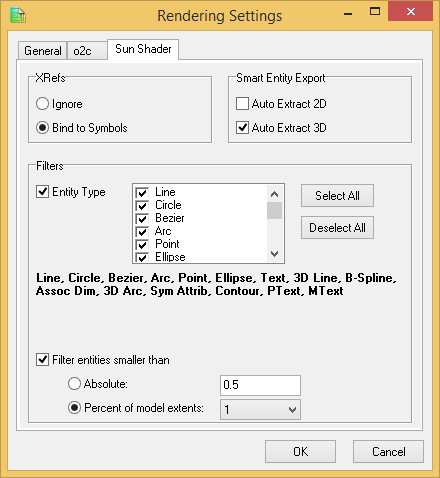
The “Rendering Settings” dialog for the Sun Shader contains new “Entity
Type” and “Entity Size” filters, which can selectively omit information
from the model to improve display speed. You can filter certain types
of entities, such as Revolved Surfaces or Cones, or you can filter entities
by size, whether absolute or relative to the rest of the model.
Render Selected Entities
The Sun Shader has two new methods of rendering selected information,
instead of your entire model: using the Clipboard, and rendering symbols.
To render information from the Clipboard in the Sun Shader: 1.Press
[Ctrl]+[e] on the keyboard, or choose “Clipboard Select” from the “View”
pull-down menu.
2.Select the information you wish to launch into the Sun Shader, by
Entity, Group, Area or Fence.
3.Click the “Display Model in Sun Shader” button on the “Rendering”
toolbar to launch the Sun Shader. DataCAD displays only the selected
information in the Sun Shader.
To render a specific symbol in the Sun Shader:
1.Display the Symbol Browser by pressing [Ctrl]+[t] or by selecting
“Symbol Browser” in the “View” pull-down menu.
2.Right-click on the symbol you wish to display in the Sun Shader, and
then choose “Sun Shader” from the context menu. DataCAD opens the selected
symbol in the Sun Shader.
 New
Settings
New
Settings
The Sun Shader has some new settings designed to improve the shadow
study results.
Custom Time Window
You now have the ability to define a custom time window for shadow studies.
Previously, only Sunrise to Sunset was supported. This option is on
the “Date and Time” tab under “Shadow Study Settings.”
Frequency
The smallest time interval for "Frequency" on the "Date and Time" tab
of Shadow Study Settings is now 5 minutes. The 6 hour interval has been
removed.
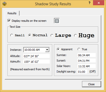
Customizable Font Size
The size of the text which displays the Shadow Study Results can now
be customized.
Miscellaneous
Support for alpha channel in transparent bitmaps has been restored.
Note: Transparent bitmaps cannot be supported while shadows are being
cast.
Pressing [Alt] + [x] locks rotation about the X-axis.
Pressing [Alt] + [z] locks rotation about the Z-axis.
New Configuration Settings
There are two new configuration settings related to the Sun Shader.
After closing all drawings and then exiting DataCAD, open the “dcadwin.ini”
file, located in the DataCAD 16\ installation folder on your C drive,
to make changes. Note: You should make a backup copy of dcadwin.ini
prior to editing, in case you need to return the program to its previous
state.
[Sun Shader]
Force Solid Background=TRUE
When FALSE (or absent) the Sun Shader background uses a gradient.
When TRUE, the background uses a solid color.
[Sun Shader]
Force Ground Plane display for Shadow Study=FALSE
When TRUE (or absent) the Sun Shader includes a ground plane when Shadow
Study mode is activated.
When FALSE, no ground plane is used.
3D Modeling and Viewing Enhancements
Inserting a symbol in a non-plan view with "Current View" toggled
on now supports using the “Nearest” Object Snapping option.
The ability to access the "Primary Divisions" and "Secondary Divisions"
on a 3D Mesh entity has been added to the Entity Properties Editor.
 "Show
Edge" and "Hide Edge" options are now available in the 3D Polygons/Edit
menu, enabling you to select individual polygon edges to show or hide.
"Show
Edge" and "Hide Edge" options are now available in the 3D Polygons/Edit
menu, enabling you to select individual polygon edges to show or hide.
 There
are new fields labeled "X Rotation," "Y Rotation," and "Z Rotation"
in the Entity Properties Editor for Polylines.Use these fields to check
or adjust the X, Y, and Z rotation angles of the selected polyline entity.
There
are new fields labeled "X Rotation," "Y Rotation," and "Z Rotation"
in the Entity Properties Editor for Polylines.Use these fields to check
or adjust the X, Y, and Z rotation angles of the selected polyline entity.
Note: When all of these values are not zero, you must use the 'Get Construction
Plane' menu before you can edit the Polyline. Otherwise, the error message
"You must be in this Polyline's construction plane to perform this function"
will be displayed when you try to use the Polyline editing tools.
![]() The
"Viewer" toolbar buttons have changed. Rotate +/- Y has been removed.
Rotate +/- Z previously rotated relative to the screen, but now rotates
using "world" Z. The default rotation angle, previously 30°, has been
changed to 5°. This is now consistent with the same toolbars in the
Object Viewer and the Sun Shader.
The
"Viewer" toolbar buttons have changed. Rotate +/- Y has been removed.
Rotate +/- Z previously rotated relative to the screen, but now rotates
using "world" Z. The default rotation angle, previously 30°, has been
changed to 5°. This is now consistent with the same toolbars in the
Object Viewer and the Sun Shader.
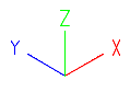 The
appearance of the 3D cursor has been updated to display the X, Y, and
Z axes in red, blue, and green respectively. These colors remain independent
of the current color.
The
appearance of the 3D cursor has been updated to display the X, Y, and
Z axes in red, blue, and green respectively. These colors remain independent
of the current color.
The “Add Vertex” and “Move Vertex” commands in the Polyline/Edit, 3D
Polygon/Edit and 3D Slab/Edit menus have been enhanced. DataCAD will
highlight the selected polyline, polygon or slab with a dashed gray
line type. If multiple edges or nodes are found within the miss distance,
you may right-click and then select again to cycle through the coincident
entities.
If you convert a polygon to a polyline, edit it, and then explode it
back to polygons, faces that have four or more sides will no longer
be triangulated.
New Configuration Settings
DataCAD 16 contains new configuration settings designed to improve
program speed and functionality, while simultaneously improving productivity.
After closing all drawings and then exiting DataCAD, open the “dcadwin.ini”
file, located in the DataCAD 16\ installation folder on your C drive,
to make changes.
Note: You should make a backup copy of dcadwin.ini prior to editing,
in case you need to return the program to its previous state.
Show Hatch
The following key will disable the display of hatching during any dynamic
drag operation:
[General]
Show Hatch During Drag=FALSE
When FALSE (default) or absent, display of hatch is suppressed while
performing a dynamic operation, such as Move/Drag, Copy/Drag or when
inserting a symbol. When TRUE, all hatch is displayed during dynamic
operations.
Line Weight Hot Key
The following key disables the [w] key on the keyboard: [General] Disable
Line Weight Hot Key=FALSE When TRUE, the [w] key on the keyboard is
disabled. When FALSE (default), pressing the [w] key increases the value
of the current line weight by 1.
Drawing Timer
The following key will keep the drawing timer running even if DataCAD
is not the active application:
[General]
No Timer Pause=FALSE
When TRUE, DataCAD will continue to increment its drawing timers even
if it is not the active application.
When FALSE (default), the drawing timers are paused if DataCAD is not
the active application.
Printing
The following key will disable the Spacebar while the Plot Preview window
is displayed:
[Plot Preview]
No Spacebar=TRUE
When FALSE or absent, pressing the Spacebar while the Plot Preview window
is displayed will result in DataCAD selecting the current active button,
which is the "Plot" button.
The following set of keys can be used to define whether display menu
settings affect the ability to print different drawing elements:
[Printer]
Print Text=DEFAULT
Print Hatch=DEFAULT
Print Line Weight=DEFAULT
Print Line Types=DEFAULT
Print Associative Dimensions=DEFAULT
Print Fills= DEFAULT
Print Bitmaps=DEFAULT
Print KnockOuts=DEFAULT
Print Smart Wall Hatch=DEFAULT
Print Smart Wall Fill=DEFAULT
![]()
Set any of the above to TRUE to force them to print, even if the attribute
setting in the Utility/Display menu is turned off. If set to DEFAULT
or missing, the drawing's display toggles T, H, L, U, D, F, B, and K
in SWOTHLUDFBK will be used to determine whether or not the element
is included in the printed output.
Display Speed
The speed of the display regeneration has been improved by up to 100%.
The improvement is most noticeable when switching between GoTo Views
or forcing a screen regeneration by pressing the [u] key on the keyboard.
In the event that these changes cause unintended effects, they can be
disabled using the following key:
[General]
New Smart Object Generation=FALSE
When absent or TRUE (default), DataCAD uses the new faster method of
screen regeneration.
When FALSE, the older method is used.
We recommend using this key to disable the speed enhancement only after
consulting with a DataCAD support technician.
Fence Selection
Fence selection now supports the same automatic crossing option used
in Area selection. Creating a Fence by clicking points in a counter-clockwise
order results in DataCAD automatically enabling "Crossing." Selecting
the points in a clockwise order leaves "Crossing" off. The order and
position of the first three selected points determines whether it is
clockwise or counter-clockwise. This feature requires the following
key be enabled in dcadwin.ini:
[General]
Automatic Crossing Selection=TRUE
When FALSE, the direction in which you choose Area or Fence points has
no effect on whether Crossing is enabled; you must manually toggle Crossing
on if you wish to use it.
The manner in which symbols are selected when using "Fence" with "Crossing"
enabled has been adjusted. Previously, the symbol would only be selected
if the insertion point was within the Fence boundary, even with "Crossing"
turned on. Now, the symbol will be selected if the Fence boundary crosses
any part of the symbol, similar to the way Area/Crossing selection works.
There is a dcadwin.ini key that can restore the command to its previous
state:
[General]
New Crossing Fence=FALSE
When absent or TRUE (default), DataCAD uses the new Fence/Crossing selection
method on symbols.
When FALSE, DataCAD uses the previous Fence/Crossing selection method
on symbols.
![]()
Busy Cursor
Use the following key to specify DataCAD's busy animated cursor:
Windows cursors, .CUR, and animated cursors, .ANI, are located in C:\Windows\Cursors\
by default.
[General]
Busy Cursor=GoldenMean
Type the name of the cursor you wish to use for DataCAD’s busy cursor
after the equal sign.
o2c Viewer
You can add the following entries to the [o2cViewer] section of DCADWIN.INI
to customize the rotation of the model and/or the texture about the
o2c world Z-axis:
Set Model_Z_Angle to 180 to orient the model consistent with o2c's coordinate
system.
Set Texture_Z_Angle to 90 to orient bitmap textures on horizontal surfaces
to match the orientation of the source image that is read from the hard
drive.
Note: The texture angle should be added to the model angle so they rotate
'together'. The default values; no rotation. Range: 0 - 360.
[o2cViewer]
Model_Z_Angle=0
Texture_Z_Angle=0
Recommended values for 'correct' orientation.
[o2cViewer]
Model_Z_Angle=180
Texture_Z_Angle=270
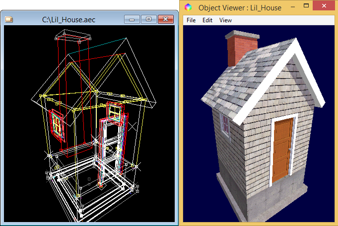 The
ability to load the current DataCAD perspective view when launching
the Object Viewer has been added.
The
ability to load the current DataCAD perspective view when launching
the Object Viewer has been added.
Note: “Remember Last View” must be set to FALSE, otherwise the last
o2c view will be restored instead.
[o2cViewer]
LoadDataCADView=True
When TRUE, the o2c Object Viewer will open using DataCAD’s current perspective
view.
When FALSE, the o2c Object Viewer opens using its standard default view.
New Extended Character Codes
The following extended character codes have been added:
Extended character codes are used when programming icon toolbars and
keyboard macros. When using any of the following new extended character
codes, you will use the syntax V= for a toolbar button which executes
just the one single command, A=10XX# or A=30XX# in a toolbar button
sequence that contains more than one command, or 10XX# or 30XX# in a
keyboard macro.
Text Underline and Overline
The following extended character codes can be used to define the status
of the Underline and Overline properties in the Text/Font dialog:
1089: Underline On
1090: Underline Off
1091: Overline On
1092: Overline Off
DWG Export
The following extended character codes can be used to export a DWG which
contains all layers or on layers:
3017: DWG Export, All Layers
3018: DWG Export, On Layers
Polyline Node Display
The following extended character codes can be used to set the
state of the "Draw Marks" toggle which displays (or suppresses display
of) polyline vertices:
1094: 3D Settings/DrawMarks On
1095: 3D Settings/DrawMarks Off
Revision History
Thank you for printing this page. Please feel free to contact us for further assistance. You can call our sales department at +1 (800) 394-2231, Monday through Friday from 8:00 a.m. to 5:00 p.m. Eastern time or send an e-mail message to info@datacad.com.