Post off topic threads here.
#54639 by Neil Blanchard
Tue Aug 30, 2011 11:39 am
Greetings,

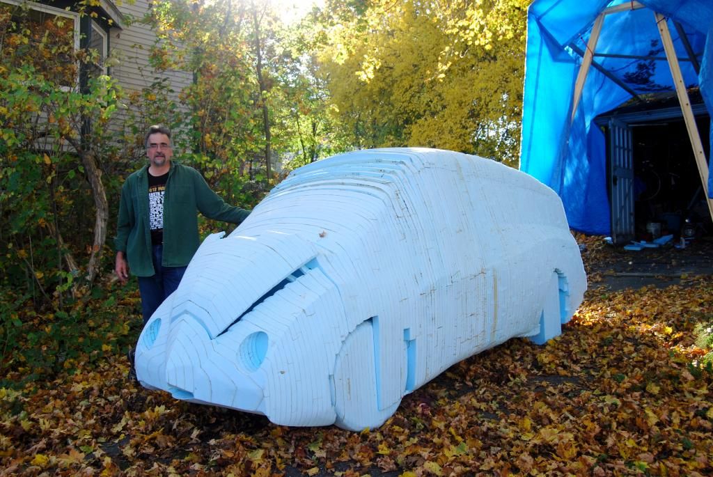
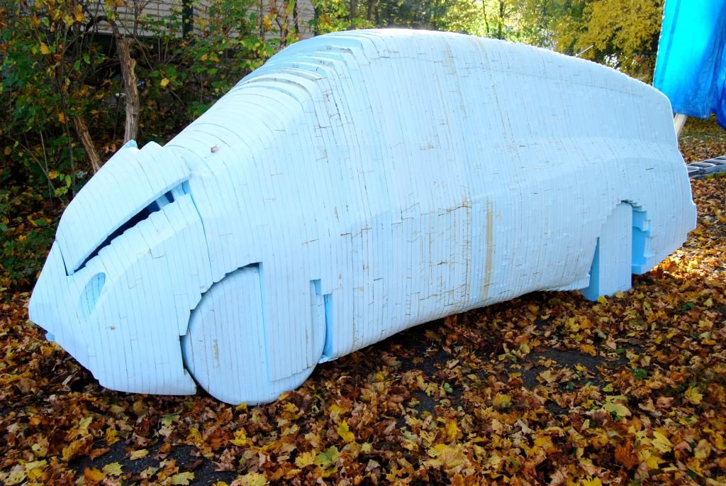
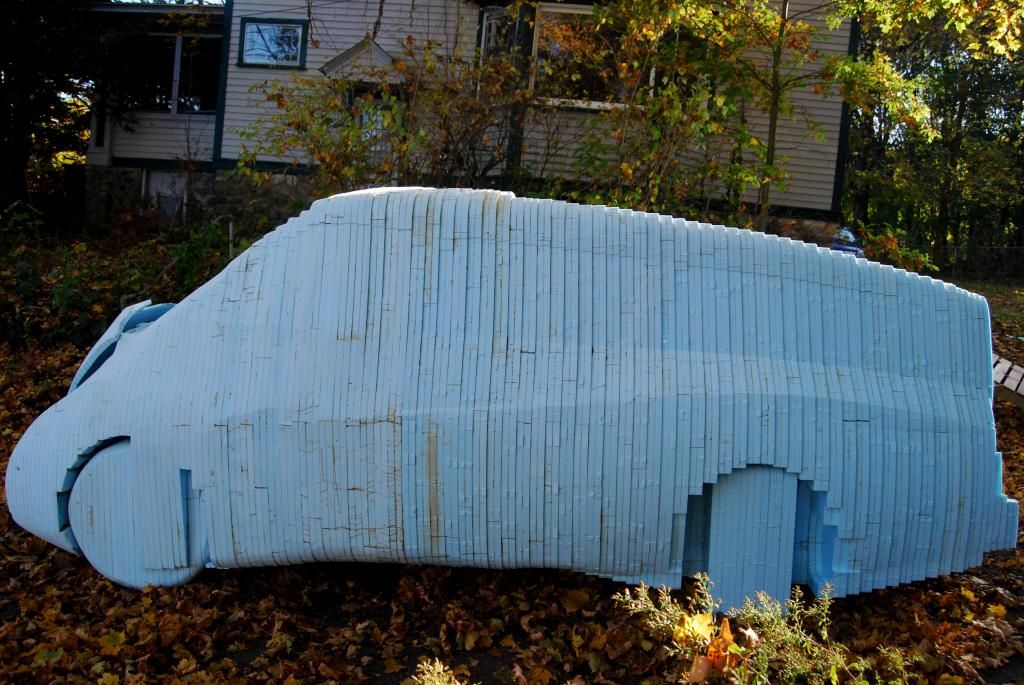
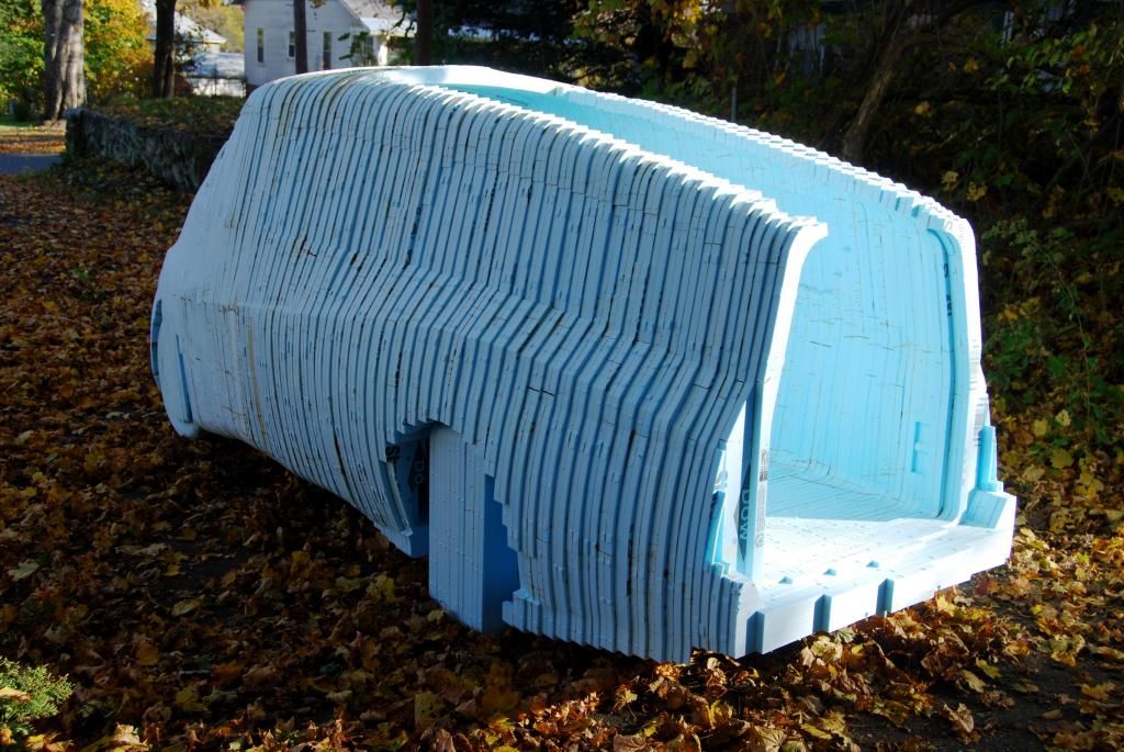
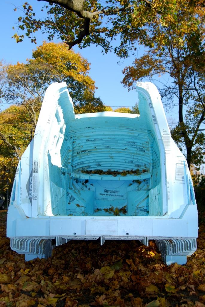
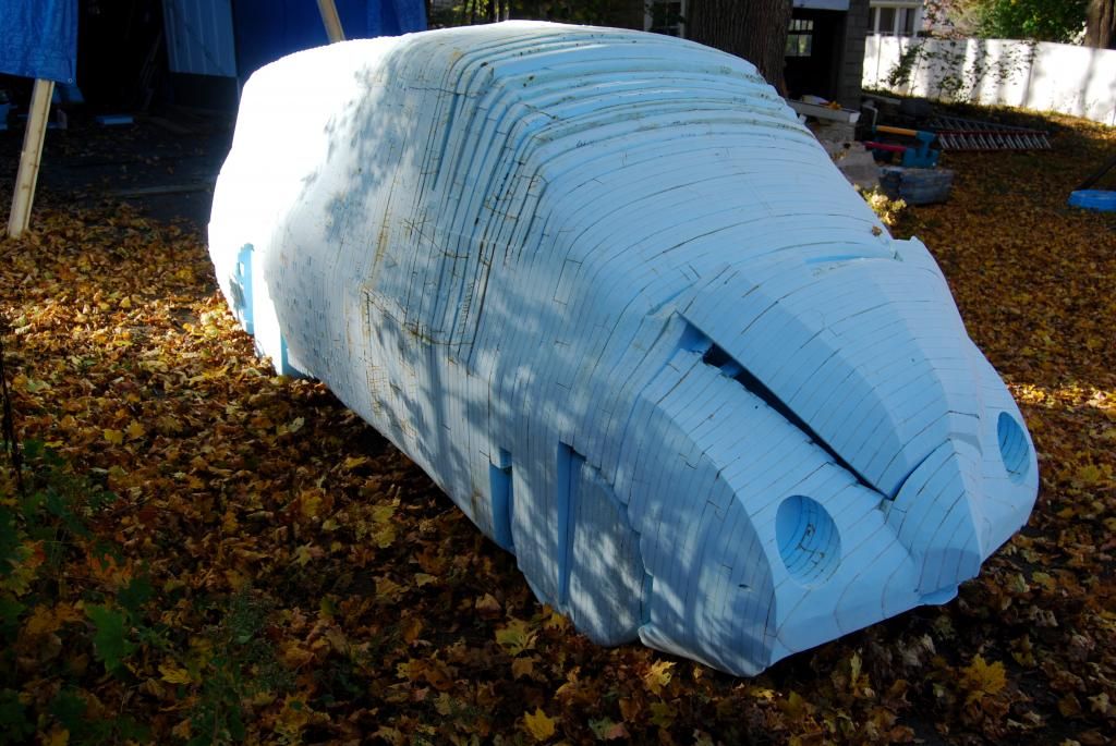
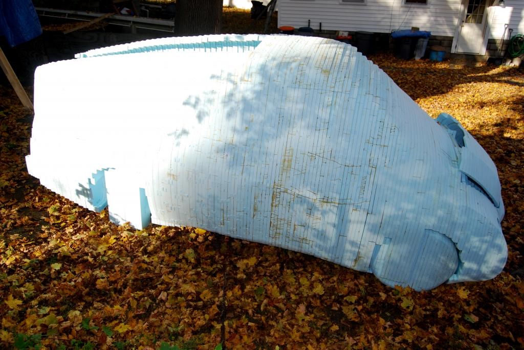
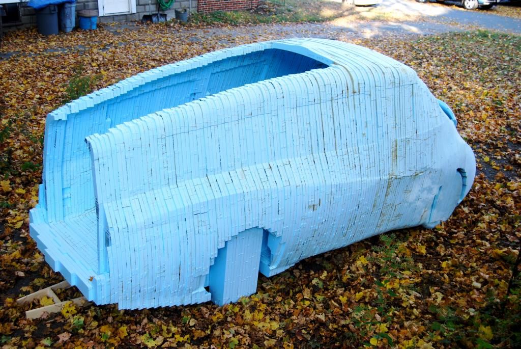
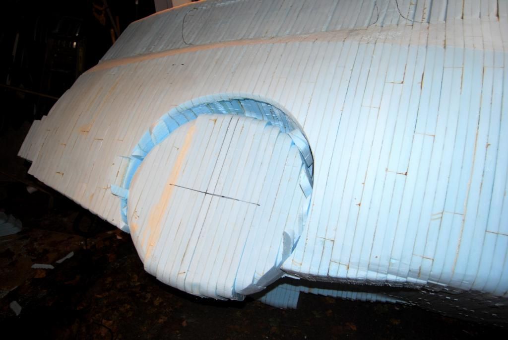
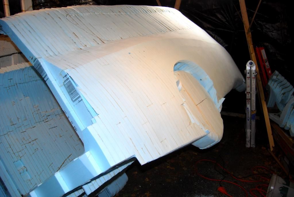
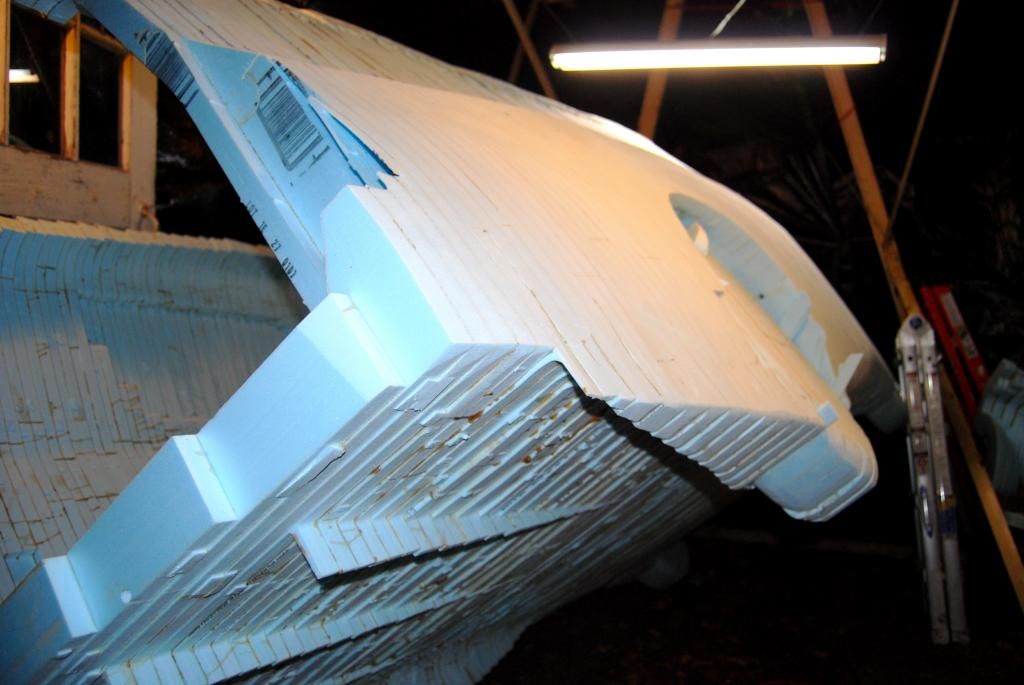
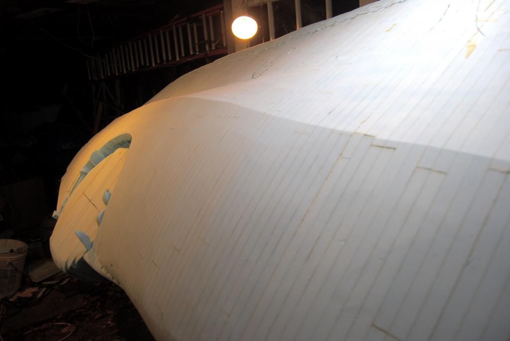
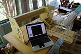
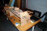
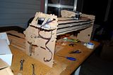
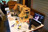
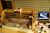
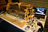
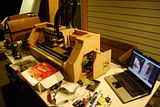
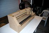
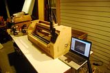
This is a 3-axis CNC machine I assembled from a kit. It cuts sheets of foam, wood, plastic, etc. from g-code files you generate from a SketchUp model. It turns a virtual model into a solid real item. I'm going to start construction of my CarBEN EV electric car.

Image Image Image Image Image Image Image Image Image Image Image Image Image Image

Video of test run:

http://www.youtube.com/watch?v=LCxENFw129E

First running of a test file (and the cutting bit is not powered up) -- you can see the yellow cone pointer showing the position of the cutter bit relative to the virtual sheet on the laptop screen; while the 3 stepper motors are putting the PhlatPrinter III through its paces, as it were.

Very cool machine -- I need to come up to speed on how to generate my own g-code files to get started constructing my CarBEN EV full sized working prototype electric car!


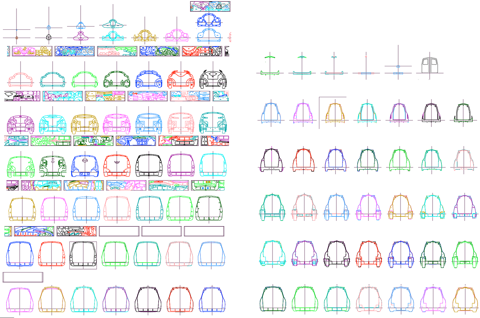
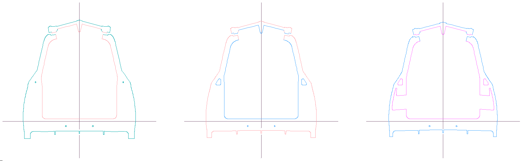
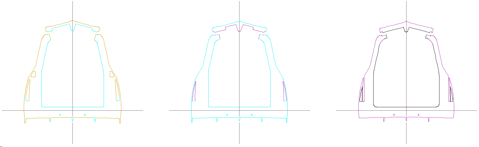
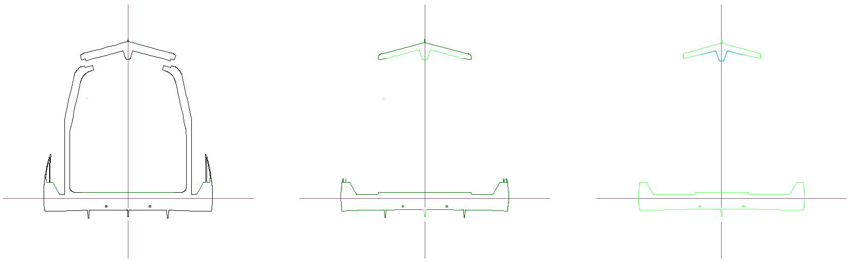
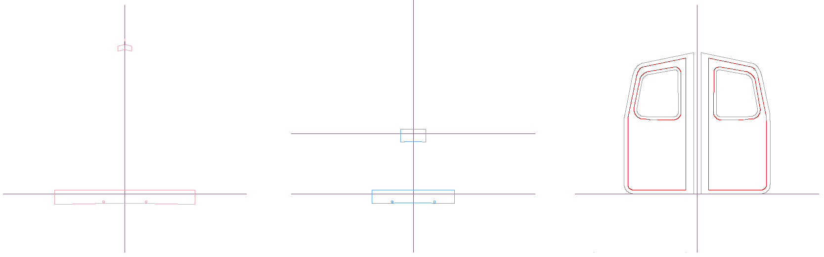
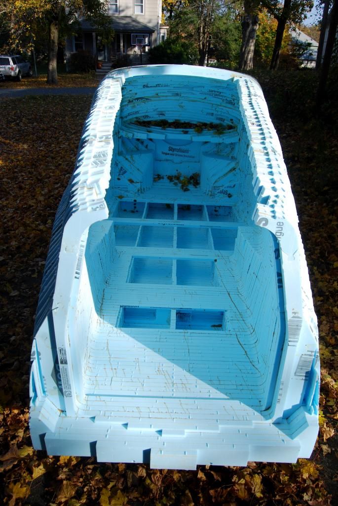
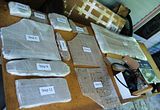
Here's a screen capture of my initial try at laying out the 2'x8' sheet of foam in DataCAD:
Image

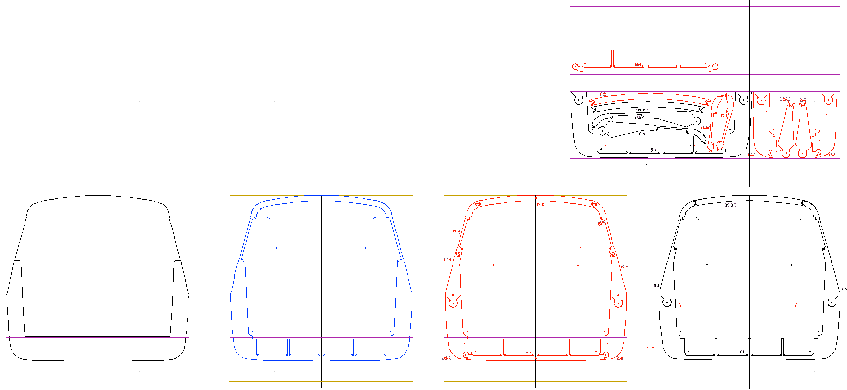
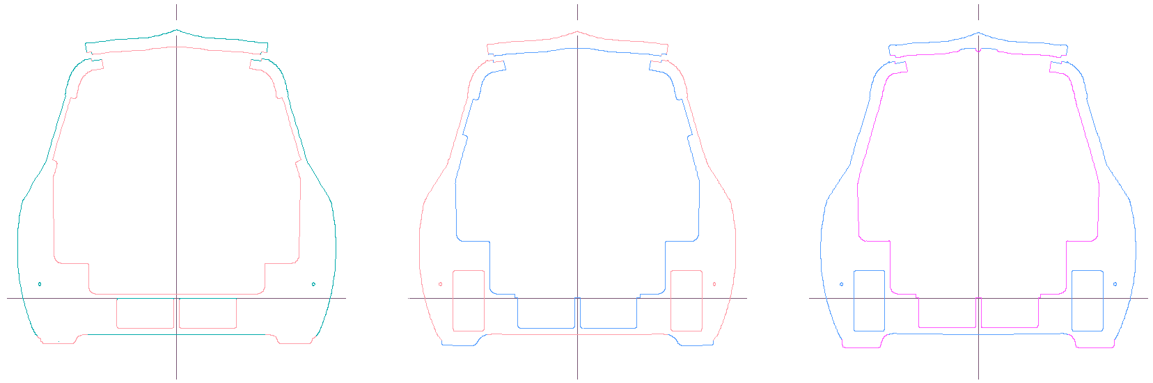
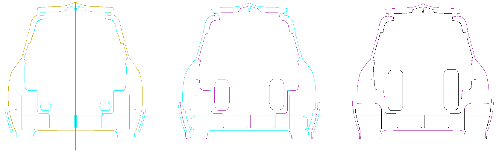
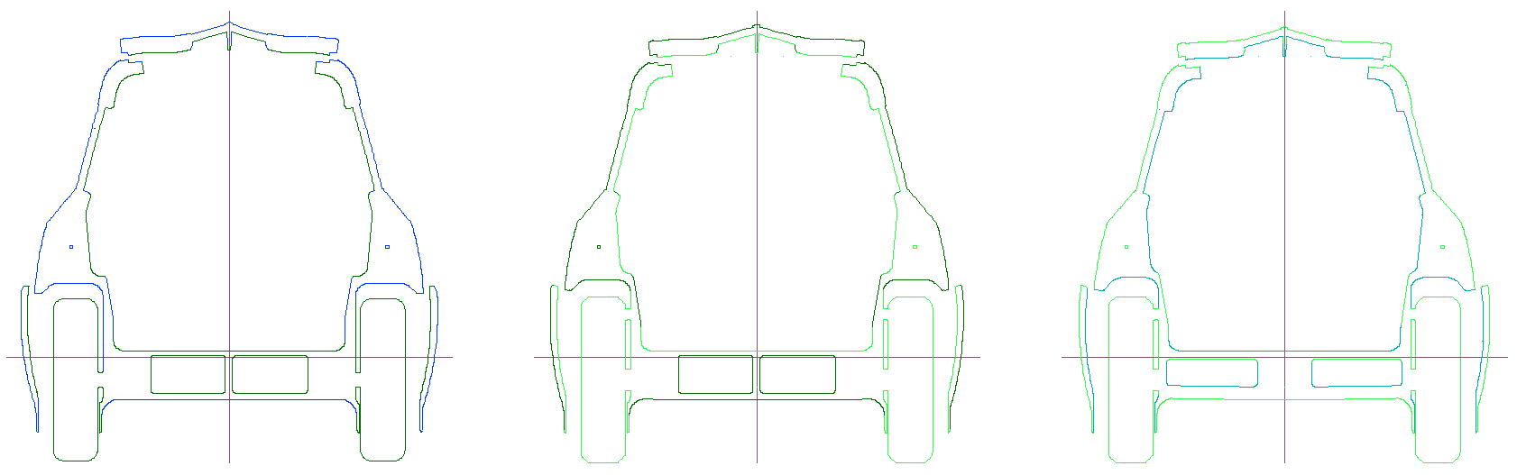
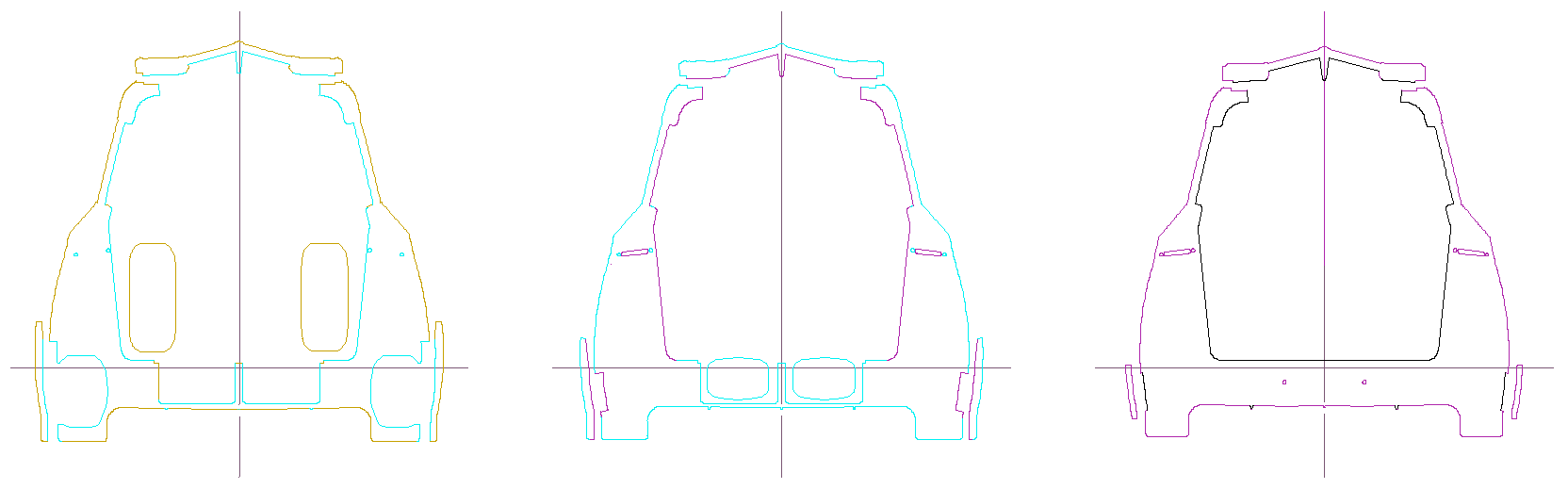
In the upper right is an approximate layout of the first 2" thick foam sheet, to be cut on on my PhlatPrinter III. I need to redo it with an alignment "rod" in the SketchUp model, that will appear as 1/2" circles, like those shown on the red F2 section. I'll use dowels to align the sections as I glue them together.

I need to confirm the limits of the cutting area -- I think the righthand edge needs a 4" band (on the 2' side) so that the X-axis friction rollers can keep hold of the sheet? And that means the F2-5 red piece will need to be moved up to the second 2'x8' foam sheet.

I also need to separate the doors, hood, wheel skirts, etc. so they can be made as pieces, and I'll have to design hinges for all of them.
Last edited by Neil Blanchard on Wed Jan 04, 2012 8:13 am, edited 1 time in total.
#55496 by Neil Blanchard
Thu Oct 06, 2011 8:52 am
A small update on CarBEN EV5: one step forward and two steps back on using the PhlatPrinter 3, unfortunately. It was working but I was having trouble with the sheet of foam skewing i.e. drifting so the second cut pass was not lining up with the first. I think I have the solution for that (side rails with rollers to hold the sheet straight) and I redid the layout of the parts on the sheet to reduce the length of the cuts, and to add attachment tabs so the bit lifted up out of the foam regularly to both cool it and to help clear the dust.

But, when I tried to run the revised sheet, the X-axis direction was "compressed" to about half of what it was supposed to be. :(

I had bought a stronger stepper motor on the X-axis (that I understood would still work with the Planet CNC driver board), and the stock motor was quite warm to the touch after this brief aborted run. The X-axis is doing a lot more work than the other two, since it has to move/accelerate the entire sheet of foam.

I decided to then install the stronger stepper motor but the motor pulsed about 3 times, and blew the fuse. So, I reinstalled the original stepper motor, replaced the fuse (2.5A) and it blew the fuse after only a second of being powered up. :( :(

Also, I have figured out that the deepest I can cut is ~1 7/8", due to the limits of the Z-axis rails on the gantry. I can live with this, but I have asked Mark and Trish the good people who designed and built the kit for the PhlatPrinter 3 whether a revised gantry could be made with ~2 1/2" of Z range could be made. This would allow there to be 2 1/4" of cutting length on the bit, so ~1/16" would stick through the sheet, ~1/8" would be above the sheet so the dust / cuttings could be cleared out, about 1/16" of straight shank out of the chuck, and there would be about 1/8" clearance on the topside when the bit is traversing.
#56406 by Neil Blanchard
Wed Jan 04, 2012 8:11 am
I've been beavering away on the DataCAD drawing for CarBEN EV5, and these are the 42 sections forward of the high point on the roof; starting at the very front of the nose:

Image Image Image Image Image Image Image Image Image Image Image Image Image

The front sections are ~1" thick because the transition is rapid, and the "stacked" sections are where I need to use a shallower depth to stop a feature. The majority of them will be 1 15/16" thick though -- there are about 85 of these, so this represents less than half -- and they are not done yet. There are five and a half sheets laid out -- I will know how many it will take to do the whole chassis when I finish this! :)

I will be using 1" thick foam sheets and just cutting two of each. This will let me use the bits I have and the machine will handle them a lot better without any farther futzing with the high current driver board and X-axis stepper motor.
#56775 by Neil Blanchard
Tue Feb 14, 2012 1:22 pm
Yeah, Aptera has been slowly damaging themselves for about 2 years...

Here's a progress image of the drafting I'm doing on my CarBEN EV5:

Image

All of the sections have now been smoothed and fleshed out; and then each section has the next section behind it copied overlaying it. This is so there is always an excess of material on all sections, so they can be smoothed just by carving with no filling needed. And the rear doors are laid out flat by cutting a section parallel through them -- they are in a slight angle, so they form a flat V.
#56794 by Neil Blanchard
Fri Feb 17, 2012 11:15 am
I've reached a benchmark on the drafting -- all the sections are drawn in their finished form. The next step will be to drawing the jigsaw joints and lay out the pieces on the 2'x8' foam sheets -- this will take a while!

Here's a more detailed look at a sampling of the section starting just behind the high point of the roof moving back through the CarBEN EV5 chassis.

Image
The different colors show the areas where the adjacent section behind adds material to the forward section. In other words, the tapered shape must have an excess of material -- because both the outside and the inside of the same taper.

I hope this makes sense.

Image
These are the sections at the top hinge of the hatch door. I've started the interlocking lip on the door and the opening that holds the seal and acts as a water gutter when the door is open.

Also, note the 1/2" diameter alignment dowel holes -- these are modeled straight through the entire model. As the chassis tapers, I added other alignment holes.

Image
These sections show the transition in side windows -- the 'C' pillar that is just ahead of the rear wheels. I'm intending the have 2 layers of glazing on the side windows and the hatch and door windows, to provide more insulation.

The section on the right has the front top of the hatch windows, near the center.

The two center rectangles in the floor are the battery bays. The vertical rectangles on the center and right section are for the rear suspension; which is probably going to be a trailing swing arm(s).

Image
These section have the front pieces of the rear wheels and the wheel skirts. Notice the hatch window is getting wider the closer you get the back.

I moved the wheels to where they may fit more efficiently when cutting the foam. And the rear shock / spring units will probably be located here.

Image
The rear wheels are attached to the chassis here, for the purposes of building the model so it can sit on the ground as the car will. After the chassis is (started?) to be fiberglassed, the wheels will be cut out and the suspension components can be designed and have the anchors affixed to the chassis.

The section on the right has voids for where a lateral link arm can be located. This will form a box beam across the floor between the rear wheels.

Image
These sections are at the back of the rear wheels, and I moved them where they fit efficiently on the foam sheets.

I am hoping to be able to use the alignment holes as a wire chase, so I am cutting a connecting channel from the outer hols to the inner holes that pass through the section closer to the back.

Image
These sections show the rear wheel strakes and the diffuser fins on the underside of the chassis. Also, I'm cutting a small area so the tail lights can be wired -- the small triangular holes at the "shoulder".

The rear exhaust air vents (that exit flush to the sides of the rear fenders) are shown in the section on the right.

Image
These sections show the exhaust air vents and the end of the rear wheel strakes. Also, the hatch windows stops at this point.

This is the 'D' pillar and the outer edges of the rear bumper starts on the section on the right.

Image
This is the very back of the chassis (nearly) and the section on the left has the rear door stops and the exhaust air vents. These are 1" thick sections because the taper on the very back is much "steeper".

The center rib on the hatch door will act as a supporting stop at the center of the rear doors. I also have added a small "dorsal" fin at the center of the hatch spine. This was not on the SketchUp model; though I hope to remake the SU model from these sections that is much smoother and much more complete as well with all of the interior voids included in the model.

Image
I cut sections parallel through the rear doors, so these are true size and I'll cut them from the flat foam sheets, avoiding an awkward bit of smoothing. The red lines are the actual edges of the doors and windows, and the gray lines are additional material so I can form the jambs.

The rear bumper and roof "spoiler" trailing edges are a very wide chevron, to match the way the rear doors close.
#57095 by Nick Pyner
Sun Apr 08, 2012 10:21 pm
Too few, I imagine, which is the main reason why it went belly-up. In short, not enuff suckers. I think it was always just a venture capital scam. I seem to recall that another who saw the Aptera for the silly joke it was, was Chris M. Giesselman.....


David A. Giesselman wrote:Who didn't see this one coming?

"Electric-car maker Aptera goes belly up"
#57333 by Neil Blanchard
Fri May 11, 2012 12:32 pm
Here's a couple of views of the stacked sections; mimicking the assembled cut foam pieces.

ImageImage

Please note that the door, wheel skirts, and the hood are separated from the main chassis, just as the foam will be, so they can be assembled separately.

I plan on importing this into SketchUp and smoothing it -- this will make the model much smoother and "tighter" so that hopefully I can then do CFD testing; which should give an approximate Cd (coefficient of drag).
#57859 by Neil Blanchard
Sat Jul 21, 2012 9:26 pm
I've started to do the rough shaping of the right side of the nose. The section is now 20" deep:

ImageImageImageImageImageImageImageImageImageImageImageImageImageImage

I have all four variants of the Stanley SurForm tools and they all are useful. The long ones are helpful on the large convex surfaces, and the palm size one is for more "precision" and the smallest convex one helps a lot when the car surface is concave.

Monday I borrow my brother's Tacoma and buy another 24 sheets of foam!
#57860 by MtnArch
Sat Jul 21, 2012 10:14 pm
This is such a great journey for you, Neil - thanks for taking us along for the ride! Good luck with the next batch of foam!!
#58075 by Neil Blanchard
Mon Aug 27, 2012 6:35 pm
I now have a 24" deep piece and a 20" deep piece -- they are held together with four 1/2" dowel rods for the moment. I have to nearly finish the shaping inside the motor bay while it is accessible from the back before I glue these together.

Image

Here is the front 44" resting on the ground -- looking kinda' like the CarBEN EV5 Ranch? ;)

ImageImageImageImage

Okay, now in the proper orientation:

ImageImageImageImageImageImageImageImageImage

As a reminder, here is the latest animated video of the SketchUp model:

[youtube]SXrqznFQ85c[/youtube]
#58076 by MtnArch
Mon Aug 27, 2012 8:51 pm
Wow - nice job, Neil! I noticed that your first post on this page was just shy of a year ago after you had assembled your CNC machine! Thanks again for allowing us to watch your journey!
#58403 by Neil Blanchard
Mon Oct 15, 2012 7:34 am
Someone on the EcoModder.com form did a really quick CFD test on CarBEN EV5 last night in a program called Falcon. Even just this brief glimpse is really cool! More to come...

http://www.flickr.com/photos/60376566@N00/8088925091

ImageImage

It uses a 3DS file which I was able to export directly from SketchUp. The way I read it, the general lack of blue on the back of the model is a good thing?

Oh, and I have been busy cutting and gluing! I only have TWO foam sheets left to cut, and the chassis is up to 10'-10" long:

ImageImageImageImage
#58502 by Neil Blanchard
Fri Oct 26, 2012 4:02 pm
Okay, I moved down into it's proper position, with the help of my son Nicolas!

ImageImageImage
ImageImageImage
ImageImageImage
ImageImage

Now I can glue up the hatch door, finish the rear wheels, the wheel skirts. I made a litter frame (you can see it in the last photo) so two people can easily carry it. I've got to batten down the shelter before Sandy gets here...
Last edited by Neil Blanchard on Fri Nov 09, 2012 9:34 am, edited 1 time in total.

Who is online

Users browsing this forum: No registered users and 39 guests

About DataCAD Forum

The DataCAD Forum is a FREE online community we provide to enhance your experience with DataCAD.

We hope you'll visit often to get answers, share ideas, and interact with other DataCAD users around the world.

DataCAD

Software for Architects Since 1984