What was new in DataCAD 10?
 How
to access the new feature
How
to access the new feature
 Helpful hints and
tips
Helpful hints and
tips
Backward Compatibility
DataCAD 10 uses the same drawing files, DCAL macros, templates, symbols, fonts, line types, hatch patterns, and layer files as DataCAD 9. DataCAD 10 also reads DataCAD 4, through 9 drawing files as well as DataCAD Plus drawing files.
Layer Manager
A new Layer Manager adds support for long layer names and allows
you to view, arrange, sort, and change layer settings within the drawing.
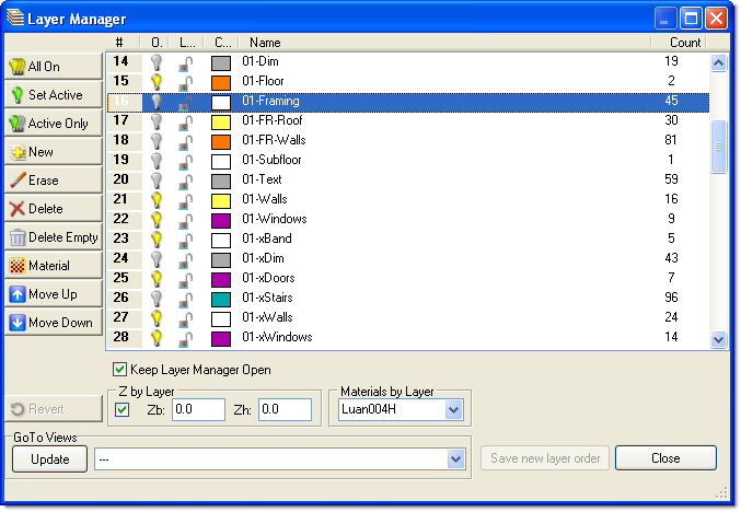
Layer Manager Dialog
Access
the Layer Manager from the Tools pull-down menu, by pressing [CTRL]
+ L, or by selecting Manage from the Layers menu.
Click on column
headings to sort layers accordingly. To make the new sort order permanent
check the Save new layer order box. To make the new sort order temporary,
leave the Save new layer order box unchecked.
Drag and Drop layers
to change their order. Hold down the [CTRL] or [Shift] key while picking
layers to select multiple layers at once.
Sorting layers will
not adversely affect GoTo Views or Multi-Scale Plot details.
Right-click in the
layer window to quickly access the Select All and Set As Active options.
Use the [Insert]
and [Delete] keys to add or delete layers.
Select Revert to
undo changes and restore the original list. You will lose all changes
made since opening the Layer Manager or selecting Apply.
Layer names may be
up to 88 characters in length. Only the first 8 characters are displayed
in the standard layer menu, but a tool tip will show the full layer
name when the cursor is passed over a button.
The display speed
and the color of the tool tip is controlled by a setting in the Misc
tab of the Program Preferences dialog.
You may view or download
the new Layer Manger Technical Bulletin directly from the DATACAD web
site.
TrueType Fonts
In addition to stroke-based fonts, DataCAD 10 adds support for Windows
TrueType Fonts.

To
access Font Settings, select Font Name from the Text menu.
Check the "Fill
using current color" option to use the active layer color for TrueType
fonts.
TrueType fonts may
have different colors for outline and fill. To select a color for either,
select Fill, Outline or Both. Uncheck the "Fill using current color"
or "Outline using current color" check boxes, then click on
the colored square to the left of the check boxes.
TrueType fonts can
be converted to 3D for use as signage in architectural models. Convert
TrueType fonts to 3D by selecting 3D Edit, Explode, ToPgons.
TrueType Fonts will
display as DataCAD CHR fonts when opened in pre-DataCAD 10 versions.
Solid, Pattern, and Bitmap Fills
In addition to vector-based DataCAD .PAT hatch patterns, DataCAD
10 adds support for Solid, Pattern, and Bitmap Fills. Unlike hatch patterns,
solid fills will display and print with the same density no matter the
viewed or plotted scale.

Select
Hatch, SPB-Fill, Settings to choose colors and patterns (SPB = Solid,
Pattern, Bitmap).
To display solid,
pattern, and bitmap fills in the drawing, first toggle Fill On and BMP
On in the Display menu.
The Status Window
indicates display setting as either f = off or F = on in SWOTHLUDFB.
The Outline boundary,
pattern and fill may have different colors. The Preview window will
show current selections.
Check the Solid Pattern
Fill box. Checking the Entity box will cause the fill to display with
the color of the polyline entity in the drawing. To change the color,
click on the colored rectangle. Select a pattern for the fill with the
Pattern option. Check the Pattern color box. Checking the Entity box
will cause the pattern to display with the color of the polyline entity
in the drawing. To change the color, click on the colored rectangle.
A bitmap image can
also be used to fill an area. Check the Bitmap Fill box, then click
on the file folder button to select the BMP or JPG image. Uncheck the
Maintain Aspect box if you want to change the X/Y aspect of the original
image. After selecting a fill or bitmap, click on OK. Pick an existing
polyline area to be filled, or draw a new area with the Boundary option.
You can control whether
solid fills and bitmaps print behind or in front of lines by using the
Print first or Print last options in the Pen Table.
Bitmap Import
DataCAD 10 supports Windows bitmap (.BMP) and JPEG (.JPG) files which
can be imported into DataCAD drawings. An unlimited number of Black
and White, Greyscale, and 8 - 32-bit color images may be referenced.

Select
Insert, Bitmap to place a BMP or JPEG file in your drawing.
Select Outline to
draw a visible polyline boundary around the inserted image.
Leave FixRatio selected
to maintain the original X/Y ratio of the inserted image. Turn it off
if you want to dynamically stretch the X or Y ratios while inserting
the bitmap. The ratio of that image cannot be changed after insertion
if FixRatio was turned on during insertion.
To display bitmaps
in the drawing toggle BMP On in the Display menu.
The Status Window
indicates display setting as either b = off or B = on in SWOTHLUDFB.
Use bitmap import
to trace scanned drawings, to display site maps, or to show digital
photos of existing building facades.
Use the new Calibrate
options in the Enlarge menu to scale bitmaps to real-world size (see
description below).
You can control whether
bitmaps print behind or in front of lines by using the Print first or
Print last options in the Pen Table.
Imported bitmaps are
referenced, not inserted into the drawing file, and do not increase
the drawing file size.
Calibrated Enlargements
New enlargement factor options have been added for enlarging or reducing
imported bitmap and vector graphics to real-world scale. For instance,
if you import a site map you can use the Calibrate Distance function
to enlarge the plan to real-world dimensions.
Select
Edit, Enlarge, Center of Enlargement, Enlrgmnt to access the new options.
Pick Cal Dist, then
select the first and second points to define the current length of an
entity, or the length of a known distance within a bitmap. DataCAD will
show you the current distance at the bottom of the screen, to the right
of the Enter new distance: prompt. The distance might be something like
1-6 3/32. Type in the distance that the two selected points should be
in the real-world, like 120 (feet). DataCAD calculates an equal X/Y
enlargement factor for you. Now select the entity or entities to be
enlarged, as you normally would. Use the Cal X-Y, Cal X, and Cal Y options
to enlarge entities independently or unequally in the X and Y directions.
o2c Object Viewer
An o2c-based Object Viewer has been added to the View pull-down menu
to provide real-time, dynamic, shaded 3D views of DataCAD models.

Select
Object Viewer from the View pull-down menu
[CTRL] + Right-click
on an entity and select o2c Settings to adjust color, opacity, and reflection
settings.
Right-click inside
the Object Viewer window and select Save Image to save a high quality
rendered bitmap of the current view in the Object Viewer window.
eZmeeting
DataCAD 10 adds direct support for eZmeeting, a third party, peer-to-peer
Internet conferencing software for CADD drawings. From the View menu
DataCAD users can launch the current view as either a 2D, 3D, or bitmap
image into an eZmeeting conference.

OpenGL Shader Enhancements
Several new enhancements to the DataCAD OpenGL Shader provide options
for creating preliminary architectural views of 3D models.
- Shadow casting
- Custom edge color and thickness
- Custom overshoot setting
- Bitmap background image
- Color Mapping

Wireframe / Shaded View
Select
Settings from the Shader menu and toggle on Cast Shadows. Check Cast
Shadow under Light Settings.
Select Shadow from
the Shader menu and select entities to receive shadows.
An entity that receives
a shadow cannot cast a shadow.
Go to Shader, Settings
for Edge and Overshoot options.
XClip (XREF Clipping)
Reference files may now have unique clipping boundaries.
From
Insert, Reference File Management select Clip Cubes. Then select the
XREF for which you want to define a new Clip Cube.
Now it is possible
to have multiple Clip Cube definitions active simultaneously and you
can enter text and dimensions outside of the XREF Clip Cube.
New Polyline Menu
A new Polyline menu has been added to the Curves menu, replacing
the Polyline macro. It incorporates new options to make the creation
and editing of polylines easier, including the ability to create voids.
Keep in mind that hatching is defined by a closed polyline, so the polyline
tools will allow you to more easily hatch your drawings.
Select
Curves, Polyline, to access the Polyline menu. Select Edit to access
additional editing features.
While in the Polyline
menu, use RectAngl or Closed to draw regular, closed polylines.
In the polyline Edit
menu, polyline vertices, edges, and curves may be edited in place.
To create voids in
polylines, first draw a master, closed polyline, then draw other closed
polylines to later be defined as voids. For instance, a building elevation
to be hatched might have a polyline created around its perimeter, then
the windows and doors would have closed polylines drawn around them.
To create and edit voids in a master polyline, select Voids, Select
master polyline to process voids. Use AddVoid to pick other polylines
to become voids in the master polyline.
To hatch a polyline
with voids, go to the Hatch menu and pick the new polyline to be hatched.
Select Polyline, Covered
to create a polyline with a closed top and bottom (for shading or rendering
purposes).
3D Edit, Explode has
ToPgons and ToSlab options to convert polylines to polygons.
To find the Area,
Perimeter or Centroid of a polyline shape, select the Area/Per option
in the Polyline, Edit menu.
Polylines support
fillets and chamfers. Select Edit, then Fillets or Chamfer to edit the
vertices of polylines.
Polylines can be filled
with hatches, solid fills or bitmaps.
Contour Search
A Contour Search option has been added to the polyline creation menus,
and allows you to easily create outlines for fills and hatches. It will
automatically search for the boundaries of a closed shape and create
a polyline around it. For instance, DataCAD could find the edges of
your walls in plan, then create a polyline for use in adding a hatch
pattern.
The
ContSrch option can be found in the Hatch, Boundary and the Curves,
Polyline menus.
Pick ContSrch, then
pick an entity along the desired boundary, or place the cursor inside
a closed group of lines, then DataCAD will try to find the lines that
create a closed perimeter. The result is a closed polyline which can
then be filled with a void, hatch, solid fill or bitmap.
HyperLink Enhancements
A new pop-up menu for creating and managing HyperLinks between drawing
entities and GoTo Views, Internet URLs, and Programs has been added.
Use
[CTRL] + Right-click while selecting an entity to access the Hyperlink
menu.
Select Goto View,
URL, or File to associate the selected entity with one of those objects.
Use Add to add a new link, Delete to delete one, or Edit to edit an
existing link.
Once an entity has
been hyperlinked to a GoTo View, [Alt] + Left click on the entity to
instantly recall the GoTo View.
To recall a hyperlinked
file or internet URL, use [Ctrl] + Right-click on a hyperlinked entity,
then pick the file or URL.
Select View, Hyperlinks
from the View pull-down menu to display all the hyperlinks in drawing.
Drawing Navigation
New hotkeys to toggle between the previous and current view respectively.
Use
[CTRL] + Left Arrow and [CTRL] + Right Arrow.
Hotspots
One click access to Color, Layer, Scale, Line type, and Selection
Set menus.
Left-click
on the text and graphics in the Status Window to access the respective
menu. A hand with a pointing finger will appear as the cursor passes
over each clickable option. Layer name = Layers menu; Scale = ToScale
menu; Line Type = Line Type menu; selection set = EditSets menu; colored
square = Color Palette dialog.
Color Palette / Color Mixer
A new color palette and color mixer have been added for selecting
and editing DataCAD color palettes. This dialog appears whenever Color,
Custom is selected.
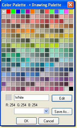

Color Palette and Color Mixer
Select
Palettes from the Tools pull-down menu.
Select any color,
or use Edit to create a custom color.
The 15 colors across
the top row are the standard 15 DataCAD colors. Clicking on a color
will display the color below, along with its color name.
Select SaveAs from
the Color Palette dialog to save custom color palettes.
This dialog will also
appear when you pick Custom from any other Color menu, like the Layers,
Color menu.
Improved DXF/DWG Support
The DXF/DWG Import
Dialogs now have local settings for Move drawing to origin, and Use
color table.
DXF/DWG Export Dialogs
now have local settings for Translate custom lines to continuous, use
color table, Explode 3D entities to 3D Faces, and Export XREFs.
DXF/DWG support added for
- Solid fills
- TrueType Fonts
- MText (paragraphed text)
- Polylines and polylines with voids
- Complex hatch patters such as StoneCAD
- Long layer names
Mouse Wheel Support

Zoom in and out using the Mouse wheel.
Press
[CTRL] and move the Mouse Wheel to zoom in and out.
Adjust settings for
the Mouse Wheel from the Misc. tab in Program Preferences.
Perspective Navigation Controls
New hotkeys and MouseWheel controls have been added to automate perspective
setup and navigation using video game-style controls.
Select Goto View,
URL, or File to associate the selected entity with one of those objects.
Use Add to add a new link, Delete to delete one, or Edit to edit an
existing link.
Use
the following hotkeys to access the walk-through commands.
[PgUp] - Walk Backward
[PgDn] - Walk Forward
MouseWheel - Walk Forward/Backward
[Up Arrow] - Walk Forward
[Dn Arrow] - Walk Backward
[Right Arrow] - Step Right
[Left Arrow] - Step Left
[SHIFT] + [Up Arrow] - Look Up
[SHIFT] + [Dn Arrow] - Look Down
[SHIFT] + [Right Arrow] - Turn Right
[SHIFT] + [Left Arrow] - Turn Left
Use the walk-through
hotkeys in any perspective view.
A new WalkThru, Options
menu allows you to customize the way you navigate.
When FixFocal is toggled
on you will always look at the same point in your model while navigating.
When FixFocal is toggled
off your focal point will move the same distance as your eye point while
navigating.
When FixFocal and FixDist
are toggled on you will navigate spherically around a fixed focal point
while navigating.
It is not possible
to turn off FixFocal and FixDist at the same time.
Turning PanView on
disables the walk through controls so you can pan and zoom your perspective
view as if it were a two-dimensional drawing.
VRML Export
DataCAD models can be exported to VRML 1.0 (Virtual Reality Markup
Language).
Select
File, Export, VRML.
The model is exported
in web-friendly 3D format, viewable with any VRML viewer.
Batch Plotting to PDF
In addition to direct printing and plot files, drawings may now be
batch plotted to Adobe Acrobat format directly from DataCAD.
Check
Plot To File(s) from the Batch Plotting Setup and set the File Format
to PDF.
Batch Plot Scripting
An enhanced scripting language allows larger firms to develop custom automated batch plotting routines.
Revision History
Thank you for printing this page. Please feel free to contact us for further assistance. You can call our sales department at +1 (800) 394-2231, Monday through Friday from 8:00 a.m. to 5:00 p.m. Eastern time or send an e-mail message to info@datacad.com.