


What's new in DataCAD 24?
DATACAD LLC
Software for Architects
www.datacad.com
Simsbury, CT 06070
USA
Sales
(860) 217-0490 Main
(800) 394-2231 Sales
info@datacad.com
Technical Support
(860) 217-0567
help@datacad.com
Free DataCAD Forum
forum.datacad.com
Dear Valued Customer:
Thank you for your interest in DataCAD 24. As part of our dedication to continuous improvement and to
deliver the highest quality CADD products possible, this latest upgrade includes your most requested
enhancements. To get the most from DataCAD 24, please refer to the overview below. If you have any
questions about DataCAD 24, contact our technical support staff at help@datacad.com.
Thank you for supporting DATACAD,

Mark F. Madura
President/CEO
mark@datacad.com
DataCAD 24 New Feature Highlights
DataCAD 24 delivers a broad set of performance and output enhancements for everyday drafting and large projects. This release improves the handling of complex drawings with extensive XREFs, Symbols, GoTo Views, and Multi-Scale Plotting Sheets; expands graphic capabilities with gradient and tiled bitmap fills; and modernizes printing with an expanded Pen Table, redesigned printer settings, and integrated DataCAD PDF Direct output.
Additional tools such as the XREF Tree, All Program Settings, PolyCleanup macro, expanded masking options, and new configuration settings provide easier customization and better troubleshooting throughout the program.
 Where to find the new
feature
 Helpful hints
Compatibility With Previous Versions
DataCAD 15 through 24 share the same drawing file format. However, you must use the Save As command in the File menu to save files backward to older version formats (11 through 14).

Large Drawing Performance
DataCAD 24 includes significant performance improvements for large and complex drawings that make extensive use of XREFs, Self-XREFs, clipped XREFs, clipped Symbols, Symbols with Layer Control, GoTo Views, and Multi-Scale Plotting Sheets.
In drawings that contain many repeated references, DataCAD now reduces redundant processing of clipping extents, layer visibility, reference calculations, and related drawing data. These optimizations are especially noticeable in drawings with hundreds of self- references that use clipping and GoTo View linking.
Operations that previously could take several minutes or more may now complete in seconds, depending on the drawing.
The performance of large drawings has been improved in the following areas:
- Opening files
- Closing and saving files
- Regenerating the display
- Displaying GoTo Views
- Opening the XREF Manager
- Entering and exiting the Print menu
- Displaying Multi-Scale Plotting Sheets
- Binding Multi-Scale Plotting Sheets
- Processing symbols with layer control enabled
These under-the-hood changes can have a measurable day-to-day impact when working on larger projects.
General Performance
Mouse Wheel Zoom has been updated to be smoother and more responsive to scrolling and direction changes.
The portion of the display pipeline that handles TrueType text has been optimized for faster
redraw of font outlines.
Expanded Imaging Enhancements
In this major update, DataCAD's graphics pipeline has been further enhanced to support greater versatility in construction and presentation documents.
Gradient Fills
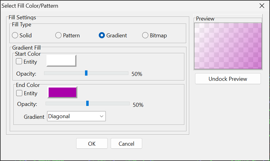
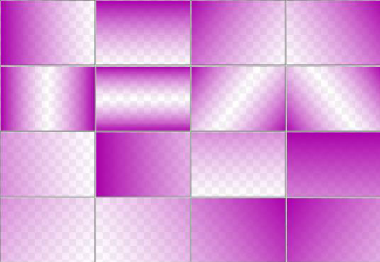
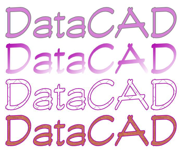
Gradient fills blend two colors and opacity levels across a boundary. Sixteen presets are available: Horizontal, Vertical, Diagonal 1, Diagonal 2, Horizontal Center, Vertical Center, Diagonal Center, Diagonal Center 2, Left, Right, Top, Bottom, Top Left, Top Right, Bottom Left, and Bottom Right.
Tiled Bitmaps
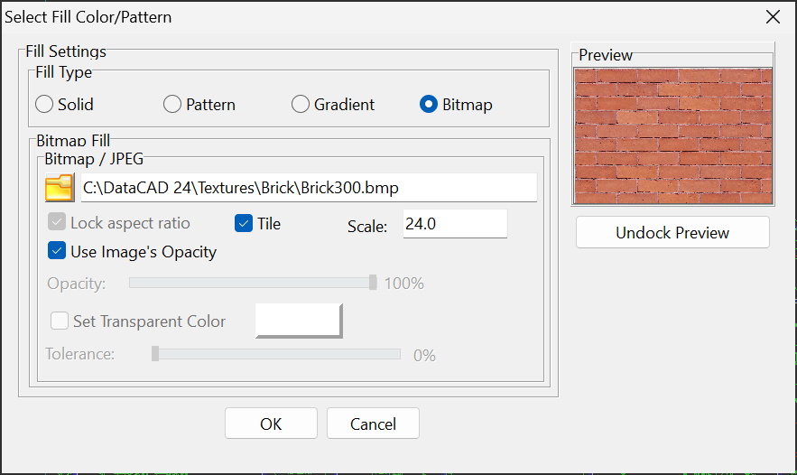
Bitmap fills can now be tiled at a user-defined size, allowing an image to repeat across a boundary like wallpaper at the interval you specify.
Enhanced Fills for TrueType Text and Smart Wall Cavities
Enhanced fill properties can now be applied to TrueType text and smart wall cavities.
Rotate Bitmaps Directly in the Drawing
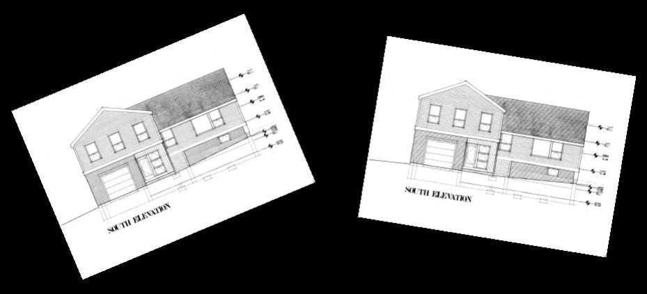
Inserted bitmaps can now be rotated directly in the drawing without having to embed them in a symbol or XREF.
Printing Enhancements and Improved PDF Creation
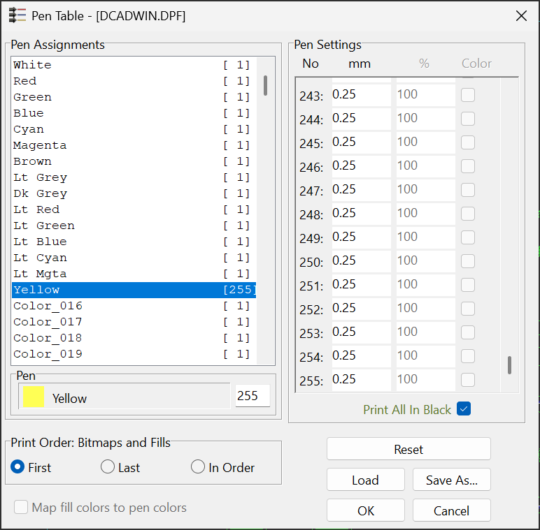
Pen Table Supports 255 Pens
The Pen Table can be configured for more than 15, and as many as 255 pens. From All Program Settings, set Pen Table Dialog : Max Pens to any value from 15 up to 255.
Revamped Printer Interface
DataCAD's printing interface receives a major upgrade in this release. The Printer Settings dialog now provides direct access to the properties of the selected device driver and lets you set the output resolution in dots per inch (dpi).
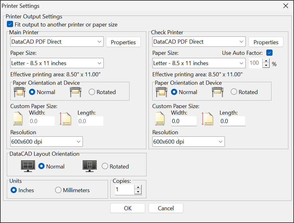
DataCAD PDF Direct
DataCAD 24 includes a built-in PDF creation interface called DataCAD PDF Direct. Select this printer to control PDF output directly in DataCAD without relying on a third-party PDF driver.
When you open a drawing created prior to 24, DataCAD checks whether the printers saved with the drawing are still available. If a saved printer is unavailable, DataCAD automatically substitutes DataCAD PDF Direct. The first time you enter the Print menu, DataCAD displays a summary of the changes.
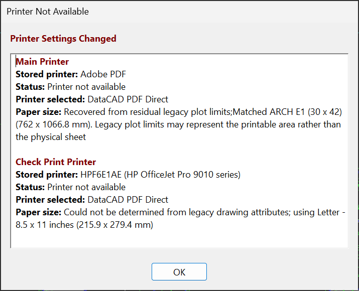
DataCAD attempts to preserve the original paper size using the best information available in the drawing:
- If complete paper information was saved, DataCAD matches the stored physical dimensions to a DataCAD PDF Direct paper size.
- If an exact named size is unavailable, DataCAD creates a custom paper size using the recovered dimensions.
- For older drawings, DataCAD examines legacy custom dimensions and saved plot limits.
- If no reliable dimensions remain, DataCAD uses the default PDF Direct paper size, normally Letter.
Recovered paper dimensions are normalized so the short edge and long edge are stored consistently. The drawing’s saved layout orientation then determines whether the Quick Layout preview is horizontal or vertical.
The notification identifies:
- The unavailable printer.
- The replacement printer.
- Whether the paper size was matched, recovered as a custom size, estimated, or could not be determined.
- Any limitations affecting the recovered printable area.
Because older drawing formats did not always store printer margins or Check Print paper dimensions, the recovered layout may not exactly match the original printer. DataCAD PDF Direct uses the full physical sheet as its printable area.
The following dialogs are used to customize PDF output and these settings are saved on a per-drawing basis.
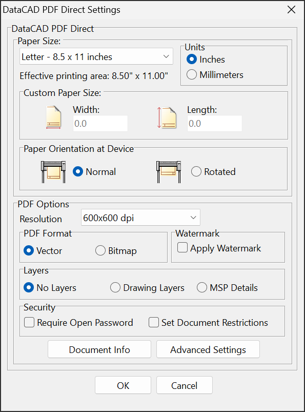
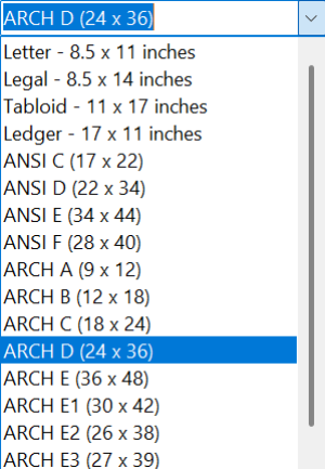
DataCAD PDF Direct provides a full complement of standard English and metric paper sizes. Output resolutions range from 72 to 4,800 dpi.
PDF Format
Previously, the selected printer driver determined DataCAD's PDF output format. With DataCAD PDF Direct, you can choose Vector (line-based) or Bitmap (raster) output. Bitmap output can be useful when you want to limit the editability of preliminary or submitted drawings.
Watermark
Previously, the watermark feature was only available via Batch Plotting and File, PDF Watermark and the settings were only accessible by editing the DCADWIN.ini file. Now you can add a watermark from the Print menu directly and customize its properties from within your drawing. See the Watermark Settings dialog below.
Layers
Previously, you could create PDF layers from drawing layers or Multi-Scale Plotting details only through Batch Plotting or Print Preview. You can now set this option directly in the Print menu.
Security
Previously, you could only add passwords and document restrictions to PDFs via Batch Plotting or via the File, PDF Security menu. Now you can establish these options directly from the Print menu. See PDF Restrictions dialog below.
Document Info
Previously, document info was added automatically based on settings that were only accessible by editing keys in DCADWIN.ini. Now you can customize these fields on a per- drawing basis with DataCAD PDF Direct. See PDF Information Settings dialog below.
Advanced Settings
Though DataCAD 24 provides access to advanced PDF settings, you should not need to adjust most of them unless instructed by a DataCAD technician. One option and a related sub-option are worth your attention. Write TrueType (not vectors), and Embed Fonts. Instead of creating PDFs where TrueType text is converted to line segments and cannot be searched, DataCAD PDF Direct now adds TrueType font names in PDFs so the text is searchable. If you’re using a custom font that allows it, you can choose to embed the font definition in the PDF so the text displays correctly for someone who does not have the font. If you’re using a font that is included with Windows, this is not necessary as the local font definition will be used.
PDF Watermark Settings
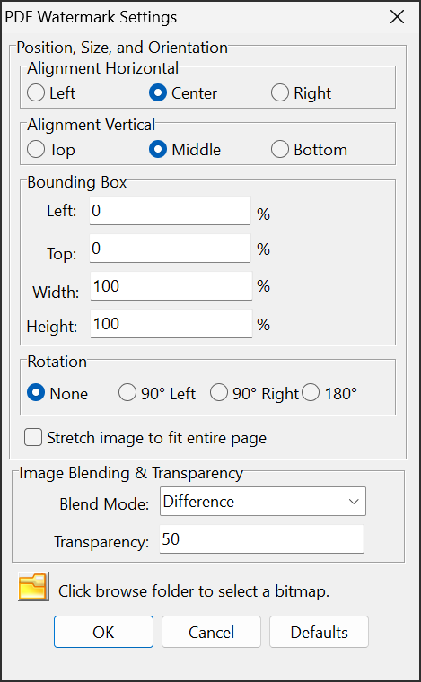
Image Align Horizontal
Sets the horizontal alignment of the image inside the bounding box. You can set the horizontal alignment to either Left, Center, or Right.
Image Align Vertical
Sets the vertical alignment of the image. You can set the vertical alignment to either Top, Middle, or Bottom.
Bounding Box
Left
Sets the left edge of the bounding box (in percent of the page) that contains the image. A value of 50 will put the left edge of the watermark at the middle of the page.
Top
Sets the top edge of the bounding box.
Width
Sets the width of the bounding box (in percent of the page) that contains the image. A value of 50 will set the width of the image box to half the width of the page.
Height
Sets the height of the bounding box.
Rotation
Set the orientation of the image as you would like it to appear on the page. Stretch image to fit entire page Use this option to automatically fit the image as large as possible within the page extents.
Blending & Transparency
Blend Mode
Can be set to one of the following values: Normal, Multiply, Screen, Overlay, Darken, Lighten, ColorDodge, ColorBurn, HardLight, SoftLight, Difference, Exclusion, Hue, Saturation, Color, or Luminosity.
Transparency
Sets transparency from 0 (completely opaque) to 100 (completely transparent).
Watermark Image
Click the folder icon to select a bitmap to use as the watermark.
PDF Information Settings
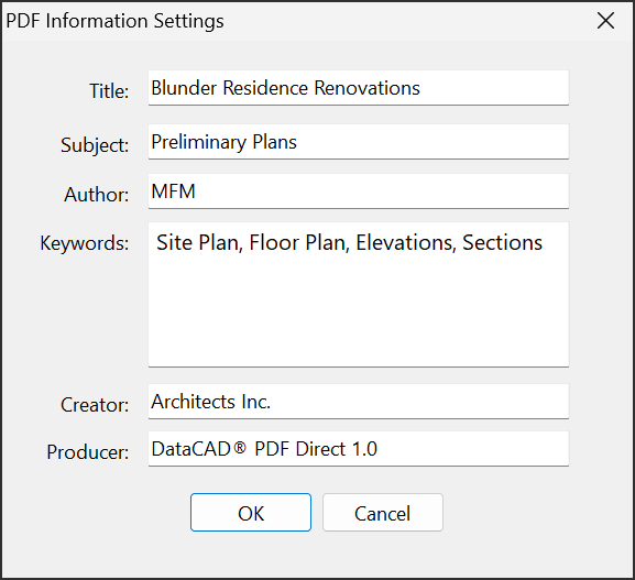
The PDF Information Settings dialog can be used to set the Title, Subject, Author, Keywords, and Creator of the document. The producer is DataCAD PDF Direct. DataCAD PDF Direct Advanced Settings
Write TrueType (not vectors)
Check this option to add font names to the document instead of vectorized characters.
Embed Fonts
Check this option to embed font definitions in the document. This will increase the size of the document. Note: Not all fonts allow embedding. If you are using standard Windows fonts, embedding fonts is unnecessary.
Enable Compression
To minimize file size, compression is enabled by default. Only disable this for troubleshooting purposes.
Buffer Commands
For best performance, command buffering is enabled by default. Disable it only for troubleshooting.
Reload Properties On New Stream
For the most reliable structuring of the graphic stack, reloading properties on a new stream is enabled by default. Only disable this for troubleshooting purposes.
Store Redundant Entity Properties
Enabling this option increases the file size and the time required to generate the document. Enable it only for troubleshooting.
Use Default App For Preview
Check this option to preview the PDF in your default viewing application. Otherwise, DataCAD's built-in PDF Preview is used.
Temporary File On Disk
The temporary file is normally maintained in memory. Only enable this for troubleshooting purposes.
Balance Page Tree
This option applies only to multi-page documents. Enable it only for troubleshooting.
Balance Content Stream
This option should only be used if the graphic stack is being improperly formatted.
Check Objects
For troubleshooting purposes. This process may take some time with large files and can consume large amounts of memory.
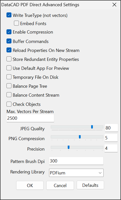
Max. Vectors Per Stream
The default value should be optimal. Only change this for troubleshooting purposes.
JPEG Quality
The default value of 80 is a good balance between size and quality. This applies to 24 bit images without transparency.
PNG Compression
The default value of 5 is a good balance between size and quality. This applies to 32 bit images that can have transparency.
Precision
The default value is a good balance between file size and accuracy. A higher number may cause objects and graphics to be more accurately positioned but will increase the file size.
Pattern Brush Dpi
Sets the resolution of pattern brushes.
Rendering Library
PDFium is the default rendering library. Only change this for troubleshooting purposes.
PDF Restrictions
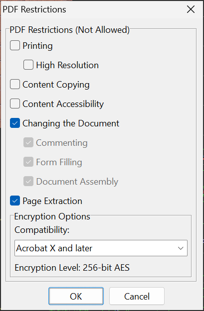
See PDF Restrictions in chapter 23 for more information.
Smart Wall Associations
When performing non-Copy or And Copy editing routines on smart walls (i.e., Move, Rotate, Mirror, and Stretch), associated doors, windows, and openings will automatically transform with the wall. New Associations are enabled by default. You can disable this behavior by setting the New Associations key in the [Smart Walls] section to False.
XREF Tree
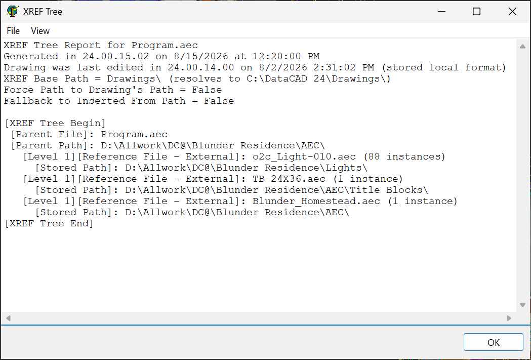
A new XREF Tree tool displays the reference hierarchy of the current drawing, making nested XREF relationships easier to understand and troubleshoot.
Automatic Screen Calibration
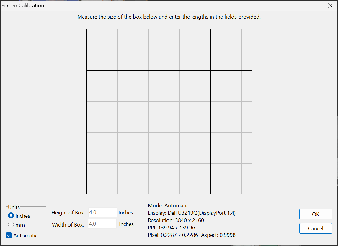
The scaling of the drawing form is now automatic. DataCAD queries the properties of your display and draws 1:1 at the current scale. You can customize the settings by unchecking Automatic in the Screen Calibration Dialog.
Drawing Repair Enhancements
The drawing repair logic has been updated to be more fault tolerant when evaluating corrupt data. Previously, invalid data identified as a deletable offense was added directly to the "do you wish to delete" list. The evaluation of invalid drawing data now includes a "can repair" pass first, so fields that can be repaired by resetting them to zero or a default value are updated before the entity is sent to the final validation pass.
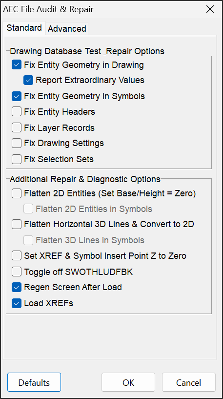
Four new options have been added:
Fix Entity Headers
DataCAD entities have a header that includes fields for color, line type, width, selection set membership, and many others. When this option is enabled, the values in each entity's header are validated, repaired if necessary, or flagged as deletable.
Fix Layer Records
DataCAD layers have a header that includes fields for on/off state, entity count, grid origin, z-base, z-height, and many others. When this option is enabled, the values in each layer's header are validated and repaired if necessary. Layers with unrepairable data are not deleted.
Fix Drawing Settings
DataCAD drawings contain more than 700 settings which include items like current dimension and text settings, the state of SWOTHLUD, printer settings, and many others. When this option is enabled, the values for each setting are validated and reset to a default value if necessary.
Fix Selection Sets
The testing and repair of selection sets was originally implemented in DataCAD 10. It’s rare for selection set data to become corrupt but this option allows you to validate them if necessary.
Flatten 3D entities has been updated to only affect 3D lines that are horizontal (same z values). Flatten 3D Lines in Symbols is now a separate option.
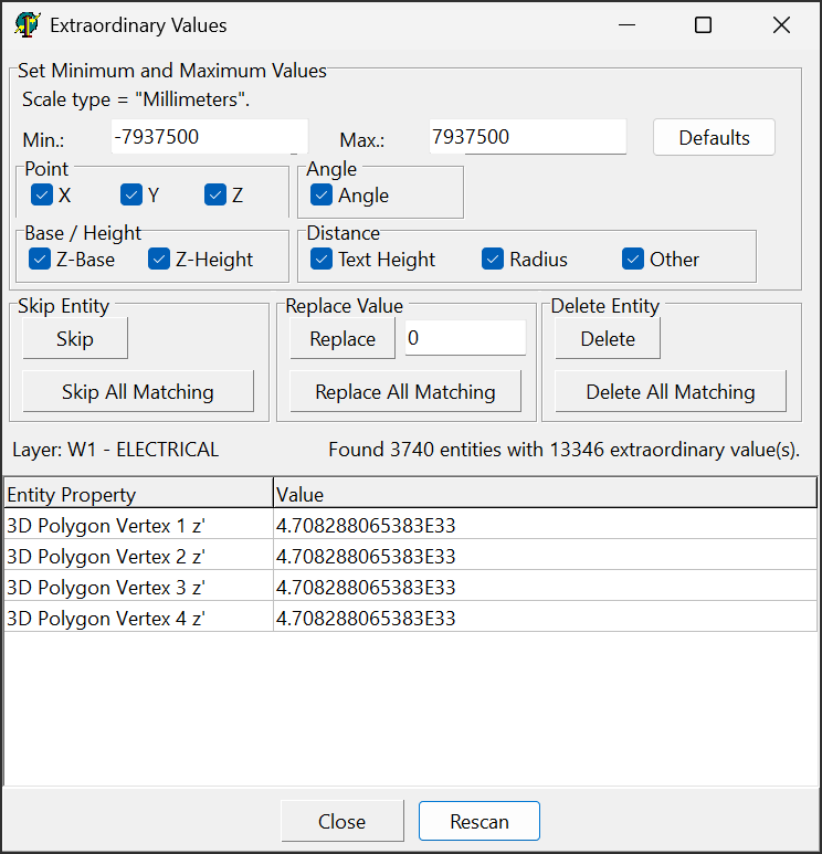
The Extraordinary Values dialog now exposes individual options for point (x, y, z) data, angles, text height, radius, and distance, in addition to z-base / z-height and reports the number of entities and corresponding extraordinary values found.
Three new sections allow you to skip the entity or all matching entities, replace the values in the entity or all matching entities, or delete the entity or all matching entities.
The audit report includes details about what invalid values were found and what the values were reset to.
All Program Settings
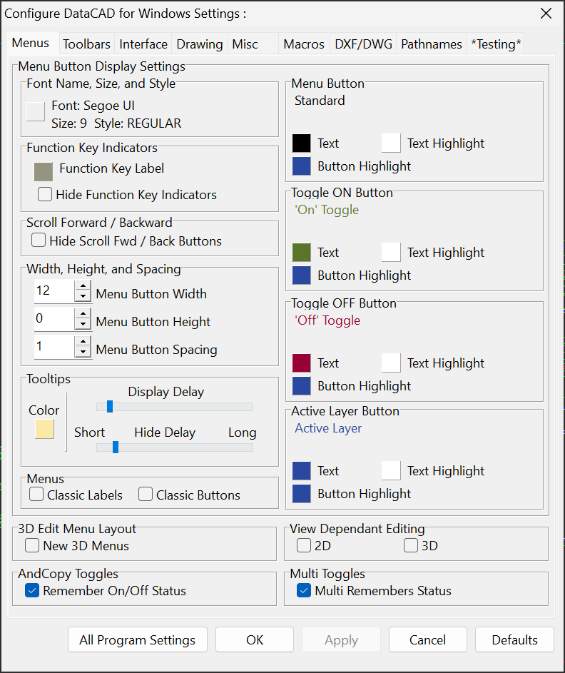
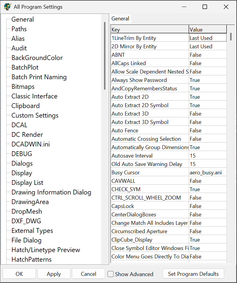
A new All Program Settings button has been added to the Program Preferences dialog. It opens a tree view of DataCAD's program settings, including settings that are not represented on the standard preference tabs.
Miscellaneous Enhancements
PolyCleanup Macro
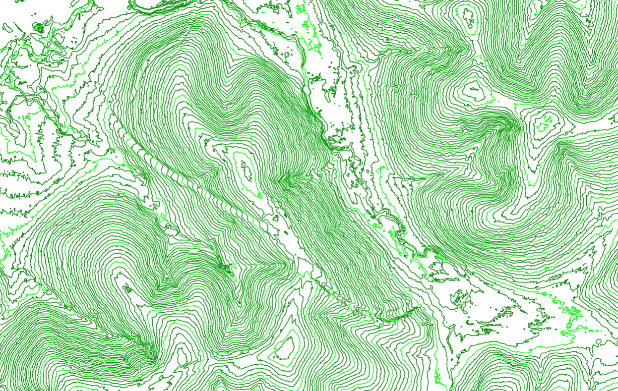
The Polyline Cleanup macro for DataCAD is a powerful tool designed to automate the cleanup and simplification of complex polylines, particularly those found in topographic maps and manufacturer symbol libraries. This macro offers options to remove redundant nodes, simplify geometries, flatten unnecessary bulges, and identify arc segments for conversion into bulges. The result is a more efficient and streamlined drawing.
Key Features
- Cleanup Polylines
- Operates at the drawing level and within symbols, including nested symbols.
- Duplicate Node Removal
- Identifies and removes duplicate (coincident) polyline nodes within a specified tolerance.
- Collinear Node Removal
- Detects and eliminates redundant nodes that are perfectly aligned (collinear) within a given distance, optimizing straight segments.
- Polyline Simplification
- Reduces node count using the Visvalingam-Whyatt algorithm, preserving overall shape while eliminating minor details.
- Flatten Tiny Bulges
- Converts small or imperceptible arc bulges to straight segments.
- Arc Detection
- Optionally detects nodes forming arcs and converts them into polyline bulges.
- Symbol and Void Support
- Processes polylines inside symbol definitions and recognizes voids (holes) within polylines.
- Preview & Logging
- Offers an optional preview of results before applying changes and logs detailed statistics about the cleanup process.
- Flexible Destination
- Updates original polylines or preserves the original entities by copying the modified entities to an existing or new layer, or by creating a new symbol.
Mask by Symbol and XREF Name
Symbol Name and XREF Name options have been added to the Mask by Entity menu. When toggled On, a case-insensitive search string field appears. Any occurrence of the string in a Symbol or XREF name is considered a match. So, “flura” matches all of the following:
- C:\DataCAD 24\Symbols\Electrical\Lighting\FLURA1X2.dsf
- C:\DataCAD 24\Symbols\Electrical\Lighting\FLURA1X4.dsf
- C:\DataCAD 24\Symbols\Electrical\Lighting\FLURA1X8.dsf
- C:\DataCAD 24\Symbols\Electrical\Lighting\FLURA2X2.dsf
Contour Search
A Jump Gap option has been added to the Contour Search menu, allowing you to set the
maximum search distance around line segment endpoints when creating a closed boundary.
Drawing Information Dialog
The Drawing Information dialog can now display the current Windows file associations for DataCAD file types. For example, you can confirm which copy of DCADWIN.exe is associated with AEC drawing files.

New Configuration Settings
DataCAD 24 consolidates access to program settings through the All Program Settings tree in Program Preferences. Use this view to browse settings by section and adjust the behavior of new and existing features to suit your workflow.
Section : Setting : Default Value
- Highlight : Allow Custom Highlight : False
- Set Allow Custom Highlight to True to customize the properties of the selection highlight display.
- Highlight : Color : 8
- Set Color to any valid color palette index from 1 to 255.
- Highlight : Pen Style : 4
- Set Pen Style to any valid pen style index from 1 to 27 (Solid R through Water Line S).
- Highlight : Spacing : 8.0
- Set Spacing in 32nds of an inch. The default is 8/32nds, ¼ inch, or 6.35 mm. Multiply by 0.79375 to convert to millimeters, or multiply millimeters by 1.2598425 to convert to 32nds.
- Highlight : Width : 1
- Set Width to set the line weight of the highlighted entity.
- Menu 3D Edit : To 3D Lines : False
- To display the To 3D Lines option in the 3D Explode menu, set To 3D Lines to True.
- Pen Table Dialog : Max Pens : 15
- Set Max Pens to any value from 15 through 255.
- Pen Table Dialog : Use Windows Color Dialog : True
- To use DataCAD’s Color Picker, set Use Windows Color Dialog to False.
- Pen Table Dialog : Show Full Path In Titlebar : False
- To display the fully qualified name of the current Pen Table in the title bar, set Show Full Path In Titlebar to True. Long names are shortened to show the beginning and end of the filename.
- Symbol Browser : Use Natural Sorting : False
- To enable natural sorting similar to Windows Explorer, where MySym_1 appears before MySym_10, set Use Natural Sorting to True.
- Printer : Get Default From Windows : False
- To use the Windows default printer automatically in new drawings, set Get Default From Windows to True.
- Printer : Warn On Printer Unavailable : True
- To skip the information dialog when the configured printer cannot be found, set Warn On Printer Unavailable to False. DataCAD will use DataCAD PDF Direct automatically.
- Recent File List : MaxMenuChars : 60
- Set the maximum number of characters displayed in the Recent Files menu from 34 through 255.
- Recent Folder List : MaxMenuChars : 60
- Set the maximum number of characters displayed in the Recent Folders menu from 34 through 255.
- DCAL : Preferred Macro Extension : dmx
- Set Preferred Macro Extension to dcx to favor DCAL for DOS macros over DCAL for Delphi macros with the same name.
New Extended Character Codes
Extended character codes are used when programming icon toolbars and keyboard macros. When using any of the following new extended character codes, you will use the syntax V= for a toolbar button which executes just the one single command, A=10XX# in a toolbar button sequence that contains more than one command, or 10XX# in a keyboard macro. For more information on toolbar programming, see the topic “Creating Custom Toolbars” in Chapter 30 of the DataCAD Reference Manual.
3057#Cut Wall On- Walls will be removed at door and window openings.
3058#Cut Wall Off- Walls will not be removed at door and window openings.
3059#In Wall On- Doors and windows will be centered between wall lines.
3060#In Wall Off- Doors and windows will not be centered between wall lines.
3061#One Layer On- One layer will be searched for walls to cut.
3062#One Layer Off- One layer will not be searched for walls to cut.
3063#Any Layer On- All "On" layers will be searched for walls to cut.
3064#Any Layer Off- Only the "Active" layer will be searched for walls to cut.
Revision History
Thank you for printing this page. Please feel free to contact us for further assistance. You can call our sales department at +1 (800) 394-2231, Monday through Friday from 8:00 a.m. to 5:00 p.m. Eastern time or send an e-mail message to info@datacad.com.