![]() Where to find the new feature
Where to find the new feature
![]() Helpful hints
Helpful hints
Compatibility With Previous Versions
DataCAD 18 contains a collection of new features and enhancements designed to increase your productivity. The DataCAD 18 drawing file format is currently compatible with DataCAD 17, DataCAD 16, and DataCAD 15. However, you must use the “Save As” command in the “File” menu to save files backward to older version formats.
SketchUp 2015
DataCAD 18 supports the ability to insert, export, and externally reference models from SketchUp 2015. This enables you to collaborate and share files with associates who use the latest version of SketchUp.
Symbol Attribute Enhancements
Resolving Broken Links to Databases
Starting with this version of DataCAD, a prompt will appear when the
database associated with a symbol text attribute cannot be found. Previously,
DataCAD would always ignore the error and allow you to enter the value
manually, rather than select it from the database. You can still choose
to ignore the error, but now you have the option to search for the file
yourself in order to repair the link.

Figure 1: Unable to Find Linked Database Warning

Figure 2: Update Database Link Confirmation Dialog
If you are able to redefine the path to the file, you will then have
the option to make the change permanent. Otherwise, DataCAD will again
look to the original path for the database the next time you open the
drawing.
DataCAD will automatically search the following locations to find the
database link before prompting you to locate the file yourself.
· The original path.
· The currently configured Databases path.
· The current drawing file path.
Note: The "Pak-N-Go" command will now include any symbol
attribute database linked files. After un-packing the file, if the database
file is not in the original path, DataCAD will automatically look in
the current drawing folder, similar to the manner in which XREFs are
resolved if not found.

Figure 3: Edit Attribute Dialog
Edit Attribute Menu
A new menu item, Edit Attribute, has been added to the context menu
for Symbol Attribute Text within the Symbol Editor. When you [Ctrl]
+ Right-click on an attribute text entity, you can select this menu
item to display the Edit Symbol Attribute dialog.
You can use the fields and options in this dialog to redefine the properties
of text attributes contained within a symbol’s definition.

Figure 4: Edit Attributes Dialog
Edit Attributes Menu
A new menu item, Edit Attributes, has been added to the context menu
for symbols. When you [Ctrl] + Right-click on a symbol that contains
attribute text entities, you can select this menu item to display the
Edit/Customize Symbol Attribute dialog.
Note: For more information about using attributes,
see “Using Text Attributes for Symbols” in Chapter 13 of the DataCAD
Reference Manual.
Hyperlink to File and GoTo View
It’s now possible to hyperlink an entity in your current drawing
to a specific GoTo View in a different drawing. Once you’ve defined
the drawing and corresponding GoTo View for the entity’s hyperlink,
selecting the hyperlink will open the drawing then automatically recall
the GoTo View. This is useful for linking a wall type tag in a plan
drawing to its corresponding detail in the details file.

Figure 5: File Hyperlink Dialog

Figure 6: New File / GoTo View Hyperlink Dialog

Figure 7: File Hyperlink Showing Linked Drawing and
GoTo View
Line Type and/or Spacing by Layer
 New
options, Line Type by Layer and Line Spacing by Layer have been added
to the Layer Manager dialog. When enabled, DataCAD will set the current
line type and/or spacing on a per layer basis. You can specify the line
type and/or spacing for a given layer within the Layer Manager, however,
DataCAD will always remember the last active line type and spacing you
used for a given layer.
New
options, Line Type by Layer and Line Spacing by Layer have been added
to the Layer Manager dialog. When enabled, DataCAD will set the current
line type and/or spacing on a per layer basis. You can specify the line
type and/or spacing for a given layer within the Layer Manager, however,
DataCAD will always remember the last active line type and spacing you
used for a given layer.
![]()
New options, Line Type and Line Spacing have been added to the Move,
and Copy, To Layer menus. You can toggle these options on to set the
line type and/or spacing of the entities you are moving or copying to
a given layer.
When Line Type and/or Spacing by Layer are off, the default setting,
enabling these options will cause DataCAD to prompt you to select the
line type and/or spacing you wish to use.
When Line Type and/or Spacing by Layer are on, enabling these options
will cause DataCAD to automatically use the line type and/or spacing
currently associated with the layer.
Get Snap Enhancements
The Get Snap popup menu includes new items that will appear when
the nearest entity includes the corresponding snapping points. This
makes it easier to snap to explicit points along an entity, even when
they are not visible within the current view (i.e. off screen).
New Get Snap Options
 Get:
(X,Y) + (X,Y) Distance
Get:
(X,Y) + (X,Y) Distance
Gets a point that is offset in the x and/or y direction from the point
you snapped to.
Get: Nearest
Gets the nearest point along entity that is closest to the point you
snapped to.
Get: Radius Point
Gets the radius point of Arcs, Circles, and Ellipses that you snap to.
Get: Center of Extents
Gets the center of extents of the entity you snapped to.
Get: Centroid
Gets the centroid of polylines and polygons you snap to.
Get: Quadrant
Gets the nearest quadrant of Arcs, Circles, and Ellipses that you snap
to.
Get: Perpendicular
Gets the point along the entity you snapped to that is perpendicular
to the point you are drawing from.
Get: Tangent
Gets the point along Arcs and Circles that is tangent to the point you
are drawing from.
New 3D Edit Menus
A new set of 3D Edit Menus are available so you can have the position
of the menu buttons in the 3D Move, 3D Copy, 3D Mirror, and 3D Stretch
menus match (as closely as possible) to the positions of the menu buttons
in the 2D Move, 2D Copy, 2D Mirror, and 2D Stretch menus.
To enable the new button arrangement in the 3D Edit Menus, set the ‘New
3D Menus’ key in the [General] section of DCADWIN.INI to TRUE. The default
is FALSE, so you will not see these changes without changing the value
of this key.

Figure 11: 2D Move, New 3D Move, and 'old' 3D Move
Menus

Figure 12: 2D Copy, New 3D Copy, and 'old' 3D Copy
Menus

Figure 13: 2D Mirror, New 3D Mirror, and 'old' 3D Mirror
Menus
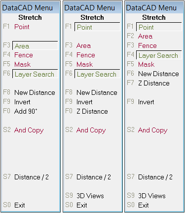
Figure 14: 2D Stretch, New 3D Stretch, and 'old' 3D
Stretch Menus
Productivity Enhancements
Save As Copy
"Save As Copy" to the "File" pull-down menu. This command will save
the changes of the current drawing session to a new file with a new
name. It differs from the "Save As" command in that it will then return
to working in the current drawing, as opposed to then opening the new
version of the file. For example, you are working in Drawing1.aec. You
choose File, Save As Copy, and then save out Drawing1_OptionA.aec. When
the process is complete, DataCAD returns you to editing Drawing1.aec.
If you had selected File, Save As to save out Drawing1_OptionA.aec,
DataCAD would have returned to editing Drawing1_OptionA.aec after completing
the command.
Coincident Entity Selection
The ability to select coincident entities when executing the Erase,
Partial command has been improved. In cases where there are two entities
that occupy the same coordinates, choose Erase, Partial and then left-click
to select the entity. If it is the wrong entity, right-click once, and
then left-click again in the same place to select the other entity.
You may now proceed with defining the segment to remove.
New & Only On
Added a new button to the 3D Hide menu labeled "New+Only On." This button
appears after the command is complete. Clicking this button results
in DataCAD setting the new layer which contains the hidden line removal
result as "Active Only," and also switches to the Plan view, enabling
you to quickly access the hidden line removal result. Prevent Windows
Screen Saver This key has been added to the
[General] section of DCADWIN.INI so you can prevent the Windows Screen
Saver from running while DataCAD is running. The default value is FALSE.
Setting this key to TRUE will disable the Windows Screen Saver when
DataCAD is running.
Prevent Windows Sleep
This key has been added to the [General] section of DCADWIN.INI so you
can prevent Windows from going to sleep or hibernating while DataCAD
is running. The default value is FALSE. Setting this key to TRUE will
disable Windows sleep and hibernate modes while DataCAD is running.
Enable XClips and/or SClips
"Enable XClips" and "Enable SClips" toggles have been added to their
respective entity context menus for convenience.
Orphaned Nested XREF Warning

Figure 15: Orphaned Nested XREF Warning
DataCAD will now issue an explicit warning to indicate the occurrence
of orphaned, nested XREFs upon opening your drawing. Previously, the
same warning applied to both orphaned XREFs and orphaned nested XREFs.
Figure 16: Orphaned XREF Warning
Identify, Set All: Smart Arrows
Selecting a Smart Arrow using Identify, Set All now toggles Smart Arrow
on in Text, Arrows.
XClip, New Cube Cursor
The XClip, New Cube cursor now disables the crosshairs while you are
creating the bounding area box.
Process XREFs
This key has been added to the [DXF_DWG] section of DCADWIN.INI to enable
(the default) or disable the conversion of XREFs during DWG export.
When the value is FALSE, DataCAD will include XREF instances in the
drawing being exported but will not convert externally-referenced files.
This option may be useful when only the parent file has changed and
externally-referenced files do not need to be re-converted.
Identify: Associative Dimension
Selecting an Associative Dimension using Identify now displays its length
on the Coordinates/Hints toolbar.

Figure 17: Actual Length of 'Decimal' Dimension Line
Shown on Coordinates / Hints Toolbar
Note: This only applies to Associative Dimensions that
have Lock Scale enabled.
Print Alias List
A new option, Print Alias List, has been added to the Select Alias dialog
box. Selecting this option will print the Alias List immediately.

Figure 18: New Print Alias List Menu
Allow Scale Dependent Nested Symbols
This key has been added to the [General] section of DCADWIN.INI to determine
whether or not the Lock Size setting of nested symbols should be recognized
or ignored. The default value is FALSE. If set to TRUE, DataCAD will
recognize the Lock Size setting of nested symbols.
 No
Scroll Forward / Backward Keys
No
Scroll Forward / Backward Keys
A new key, "No Scroll Keys", has been added to the [General] section
of DCADWIN.INI. Setting this key to TRUE, removes the Scroll Back and
Scroll Fwrd buttons from menus where they would otherwise appear. For
example, in a drawing where there are more than 15 layers, a Scroll
Fwrd button appears at [S7], while [S6] is reserved for Scroll Back.
Setting No Scroll Keys=TRUE frees up two positions in the menu list,
as the scroll wheel and [PgUp]/[PgDn] keys can be used instead.
View Layer File
The View Layer File function has been enhanced to allow 255 (increased
from 80) character file / path names.
Fix Text Toggle
The 'Fix Text' toggle has been added to the Clipboard Paste menu when
you are pasting text.
Use Significant Digits In Dialogs
This key has been added to the [General] section of DCADWIN.INI so you
can enable significant digits in DataCAD's distance edit fields shown
in dialogs. The default value is FALSE. Setting this key to TRUE will
cause the Distance edit fields in dialogs to adhere to the SigDigit
setting in the ScaleType menu.
Persistent Layer Manager Hotkey
[Ctrl] + [L] is the default key combination for opening and closing
the Layer Manager (customizable in dcadwin.mnu). This only applies to
the persistent Layer Manager.
GUI File Path
A unique path has been added to the "Pathnames" tab of Program Preferences
to define the location for "User Interface Files (.GUI)." This enables
you to store the user interface files "dcadwindialogs.gui," "dcadwintoolbars.gui,"
and "objectviewer.gui" in a path that is different from other support
files.
Color Menu Goes Directly To Dialog
This key has been added to the [General] section of DCADWIN.INI so you
can now display the Color Palette dialog in commands that would normally
display the "Color" menu.
Edit Symbol Fields Dialog

Figure 22: Edit Symbol Fields Dialog
The "Edit Fields" dialog is now displayed after choosing "Save As" from
the right-click menu of a symbol displayed in the Symbol Browser, or
from the [Ctrl] + Right-click, Symbol Tools context menu of a symbol
in the drawing area.
o2c None Materials
A set of keys have been added to the [o2cViewer] section of DCADWIN.INI
so you can customize the default "None" material settings. These settings
determine the rendered appearance of entities that do not already have
a material assigned to them.
See “New Configuration Settings” for the list of keys.
o2c Fixed Materials
A set of keys have been added to the [o2cViewer] section of DCADWIN.INI
so you can 'force' certain material settings to apply to all entities,
regardless of their currently-defined material definition. For example,
if you want all surfaces in your model to appear glossy, you might set
MatFixed Specular to 70 instead of the default value of 10. Or, if you
want everything in your model to appear transparent, you might set MatFixed
Opacity to 30 instead of the default value of 100.
See “New Configuration Settings” for the list of keys.
Note: These settings only apply at the time you launch
your model in the Object Viewer, and have no effect upon the material
definitions that are stored in the drawing.
Material XOR Background
This key has been added to the [o2cViewer] section of DCADWIN.INI to
prevent DataCAD from 'flipping' an entity's default rendered color when
it is the same as the background color. Typically, this would apply
to a white background. In this case, DataCAD will XOR the white lines
in your drawing to black so they will not 'disappear.' This causes white
entities to render black in the Object Viewer. Setting Material XOR
Background to FALSE, will cause white entities to render white, instead
of black, when you have a white background.
See “New Configuration Settings.”
Sun Shader Enhancements
 Entity
Filter
Entity
Filter
The Sun Shader entity filter now applies to entities contained within
Symbols, Smart Entities, and XREFs. The key, ‘Apply Filters To Embedded
Entities’ has been added to the [Sun Shader] section of DCADWIN.INI
to control this behavior. The default value is TRUE.
Smart Symbol Export
Added a new option to the Sun Shader tab of the View/Rendering/Settings
dialog, labeled "Smart Symbol Export." When "Auto Extract 2D" is checked,
layers inside of symbols that are assigned to display in 2D view projections
(i.e. plan) are included in the Sun Shader. When un-checked, the 2D
layers are not included. When "Auto Extract 3D" is checked, layers inside
of symbols that are assigned to display in 3D view projections (i.e.
isometric or elevation) are included in the Sun Shader. When un-checked,
the 3D layers are not included.
Miscellaneous Enhancements
· The width of the Saved Views drop-down is now defined by the length of the
longest name.
· When using File/Save Image, the path, image resolution, and image type are
now stored with the application, and remembered across sessions.
· Added the ability to reload the Sun Shader interface text without having
to restart DataCAD. This option is helpful when translating the program
interface into other languages.
Modify the following key in SunShaderNX.ini, located in the C:\DataCAD
18\Sun Shader\NX\Support Files\ folder:
[TRANSLATION]
EXPOSE INTERNATIONALIZATION TOOLS=FALSE
If TRUE, a new "[Debug] - Internationalization Tools" pull-down menu
is shown at the top of the Sun Shader interface. Click it and then choose
"Reload messages" to reload the interface text.
New Configuration Settings
DataCAD 18 contains new configuration settings designed to improve
program speed and functionality, while simultaneously improving productivity.
After closing all drawings and then exiting DataCAD, open the “dcadwin.ini”
file, located in the DataCAD 18\ installation folder on your C drive,
to make changes.
Note: You should make a backup copy of dcadwin.ini
prior to editing, in case you need to return the program to its previous
state.
[General]
New 3D Menus=FALSE
If TRUE, the position of the menu buttons in the 3D Move, 3D Copy, 3D
Mirror, and 3D Stretch menus match as closely as possible to the positions
of the menu buttons in the 2D Move, 2D Copy, 2D Mirror, and 2D Stretch
menus.
Color Menu Goes Directly To Dialog=FALSE
If TRUE, clicking "Color" (for example in the Change menu) will automatically
display the Color Palette dialog. Previously, it would display the "Color"
menu.
Prevent Windows Sleep=FALSE
If TRUE, Windows sleep and hibernate modes will be disabled while DataCAD
is running.
Prevent Windows Screen Saver=FALSE
If TRUE, the Windows Screen Saver will be disabled when DataCAD is running.
Use Significant Digits In Dialogs=FALSE
If TRUE, the Distance edit fields in dialogs will adhere to the SigDigit
setting in the ScaleType menu.
Allow Scale Dependent Nested Symbols=FALSE
If TRUE, DataCAD will recognize the Lock Size setting of nested symbols.
SaveAs Uses Current Drawing Folder=FALSE
If TRUE, DataCAD will set the path to the current drawing folder, instead
of the previous File, Open path, when you use the Save As... or Save
As Copy... commands.
No Scroll Keys=FALSE
If TRUE, the Scroll Forward and Scroll Backward buttons will not appear
in list menus with more than 15 items. Instead, up to 17 items will
be shown.
[Paths]
PATH_GUI_FILES=Support Files\
Path to store GUI (User-interface) files.
[DXF_DWG]
Process XREFs=TRUE
If FALSE, DataCAD will include XREF instances in the drawing being exported
but will not convert externally-referenced files.
[o2cViewer]
Material XOR Background=TRUE
If FALSE, white entities will render white, instead of black, when you
have a white background.
MatFixed ClrDiff_Red=
Fixed Diffuse Color for Red Component (0-255).
MatFixed ClrDiff_Green=
Fixed Diffuse Color for Green Component (0-255).
MatFixed ClrDiff_Blue=
Fixed Diffuse Color for Blue Component (0-255).
MatFixed ClrRefl_Red=
Fixed Reflection Color for Red Component (0-255).
MatFixed ClrRefl_Green=
Fixed Reflection Color for Green Component (0-255).
MatFixed ClrRefl_Blue=
Fixed Reflection Color for Blue Component (0-255).
MatFixed Reflection Ambient=
Fixed Ambient Reflection Percent (0-100).
MatFixed Reflection Diffuse=
Fixed Diffuse Reflection Percent (0-100).
MatFixed Reflection Specular=
Fixed Specular Reflection Percent (0-100).
MatFixed Highlight Size=
Fixed Highlight Size (1-200).
MatFixed Opacity=
Fixed Opacity Percent (0-100).
MatFixed Refraction=
Fixed Refraction Index (1-64 where 10 equals no refraction).
MatFixed Flags=
Fixed Material Flags
MatNone Color Diffuse=
‘None’ Material Diffuse Color (DataCAD Color Palette 1-255).
MatNone Color Reflect=
‘None’ Material Reflection Color (DataCAD Color Palette 1-255).
MatNone Reflection Ambient=50
‘None’ Material Ambient Reflection Percent (0-100).
MatNone Reflection Diffuse=40
‘None’ Material Diffuse Reflection Percent (0-100).
MatNone Reflection Specular=10
‘None’ Material Specular Reflection Percent (0-100).
MatNone Opacity=100
‘None’ Material Opacity Percent (0-100).
MatNone Refraction=10
‘None’ Material Refraction Index (1-64 where 10 equals no refraction).
MatNone Highlight Size=2
‘None’ Material Highlight Size (1-200).
MatNone Self-Illuminate=FALSE
If TRUE, ‘None’ Material is self-illuminated.
MatNone Render Backface=TRUE
If TRUE, ‘None’ Material will render both faces.
MatNone Has Texture=FALSE
If TRUE, ‘None’ Material will use assigned bitmap texture.
MatNone Texture Scale=1
‘None’ Material texture size defined in decimal meters.
MatNone Texture Name=
Name of ‘None’ Material bitmap.
MatNone Smooth Edges=TRUE
If TRUE, ‘None’ Material will smooth edges of adjacent polygons.
MatNone Texture Mask=FALSE
If TRUE, ‘None’ Texture will render black as transparent.
MatNone Texture Colorize=FALSE
If TRUE, ‘None’ Texture will colorize bitmap with diffuse color.
MatNone Texture Reflection=FALSE
If TRUE, ‘None’ Texture will reflect from surface of object.
[Sun Shader]
Apply Filters To Embedded Entities=TRUE
If TRUE, The Sun Shader entity filter will apply to entities contained
within Symbols, Smart Entities, and XREFs. This is the default behavior.
[Symbol Attributes]
New Database Linking=TRUE
If TRUE, the default, the new symbol attribute database linking features
are enabled.
Databases Have Header Row=FALSE
The default value is FALSE. If TRUE, DataCAD will assume the first row
in CSV files linked to symbol attributes is a Header row.
New Extended Character Codes
The following extended character codes have been added:
Extended character codes are used when programming icon toolbars and
keyboard macros. When using any of the following new extended character
codes, you will use the syntax V= for a toolbar button which executes
just the one single command, A=10XX# or A=30XX# in a toolbar button
sequence that contains more than one command, or 10XX# or 30XX# in a
keyboard macro. For more information on toolbar programming, see the
topic “Creating Custom Toolbars” starting on page 591 of the Reference
Manual.
1100: Reserved
New extended character codes have been added to set the state of the
Highlight setting for Classic Walls.
1101: Highlight On
1102: Highlight Off
New extended character codes have been added to set the state of Multiple
in certain editing commands.
1103: Copy Multiple On
1104: Copy Multiple Off
Note: The key, MultiRemembersStatus must be set to
TRUE in the [General] section of DCADWIN.INI.
Revision History
Thank you for printing this page. Please feel free to contact us for further assistance. You can call our sales department at +1 (800) 394-2231, Monday through Friday from 8:00 a.m. to 5:00 p.m. Eastern time or send an e-mail message to info@datacad.com.